98 Description Of Specific Functions
V560 Series High Performance Closed-Loop Vector Inverter User Manual
7. DESCRIPTION OF SPECIFIC FUNCTIONS
Remark: Unless otherwise especially instructed, the status of terminals will be defined under positive
logic conditions (“ON” terminals effective, and “OFF” terminals void).
7.1 SYSTEM MANAGEMENT (GROUP F0.0)
Group F0.0 parameters are especially used to define system control parameters, e.g. locking, initializing,
motor type and control mode as well as display of monitoring parameters, etc.
F0.0.00 Macro parameters Setting range: 0000~2006 Factory default: 0000
Macro parameters include application macro, system macro and special macro; The application macro
allows for conveniently setting and curing multiple common parameters and simplifying parameter setting for
general applications; the system macro allows for conveniently switching equipment’s work mode and
automatically defining partial parameters; The special macro allows for internal integration and settings for
special functions or parameters with one key according to typical industrial applications.
Macro parameters are not influenced by the initializing parameter F0.0.07 and partial macro-related
parameters are locked at specific value or within specific range.
_ _ _ X : Application macro
0: Void
Customized settings, all parameters can be customized without being influenced by the application macro
parameters.
1: Digital setting of keypad control
Refer to Figure 7-1 for the application wiring diagram, and refer to Table 7-1 for macro- related parameters.
2: Shuttle setting keypad control
Refer to Figure 7-1 for the application wiring diagram, and refer to Table 7-1 for macro- related parameters.
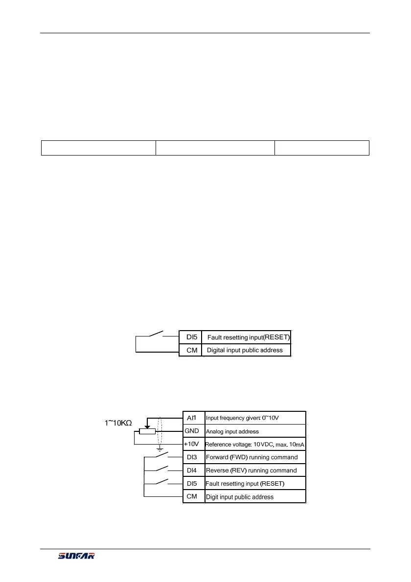
3: 2 wire Control 1/AI1 setting
Refer to Figure 7-2-A for the application wiring diagram, and refer to Table 7-1 for macro- related parameters.
Figure 7-1 Wiring diagram forpanel operation digital/shuttle setting
Figure 7-2-A 2 wire control 1/AI1 setting wiring diagram
 Loading...
