Functional Parameter Table
V560 Series High Performance Closed-Loop Vector Inverter User Manual
50
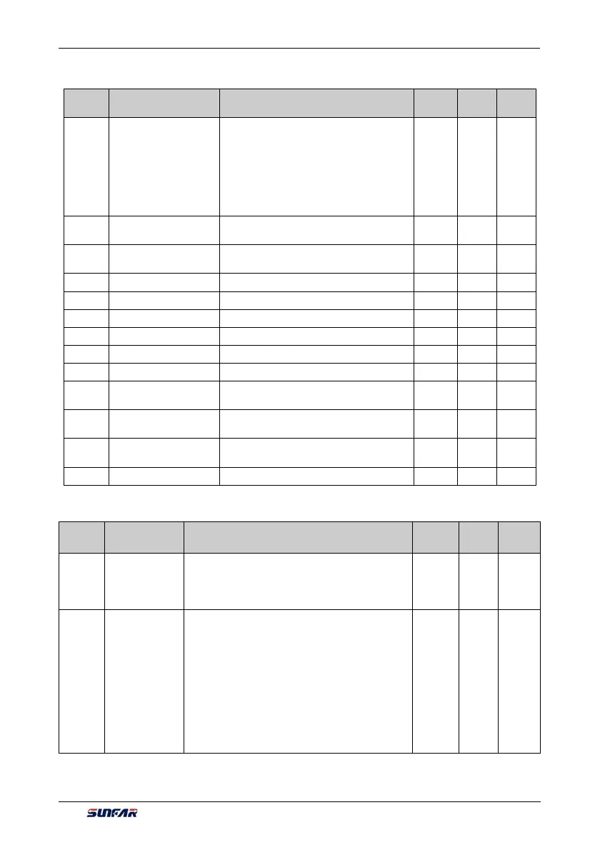
6.2.6 ACCELERATION AND DECELERATION CHARACTERISTICS PARAMETERS
Function
Code
Name Setting Range and Description
Minimum
Unit
Factory
Default
Change
Limit
F1.0.00
Acceleration and
deceleration
characteristics
parameters
_ _ _ X: Accel decele mode
0: Liner acceleration and deceleration
1: S curve acceleration and deceleration
_ _ X _: Unit of acceleration and
deceleration time
0: Sec. (Second)
1: Min. (Minute)
1 0000 ×
F1.0.01
% of S curve at the
bottom
5.0~100.0-[F1.0.02] 0.1 15.0
F1.0.02
% of S curve at mid
section
20.0~100.0-[F1.0.01] 0.1 70.0
F1.0.03 Acceleration time1 0.01~ 600.00 (Sec./Min.) 0.01 ☆
F1.0.04 Deceleration time1 0.01~ 600.00 (Sec./Min.) 0.01 ☆
F1.0.05 Acceleration time2 0.01~ 600.00 (Sec./Min.) 0.01 ☆
F1.0.06 Deceleration time2 0.01~ 600.00 (Sec./Min.) 0.01 ☆
F1.0.07 Acceleration time3 0.01~ 600.00 (Sec./Min.) 0.01 ☆
F1.0.08 Deceleration time3 0.01~ 600.00 (Sec./Min.) 0.01 ☆
F1.0.09
Acceleration 4/jog
acceleration time
0.01~ 600.00 (Sec./Min.) 0.01 ☆
F1.0.10
Deceleration 4/jog
deceleration time
0.01~ 600.00 (Sec./Min.) 0.01 ☆
F1.0.11
EMS emergency stop
and deceleration time
0.01~ 600.00 (Sec./Min.) 0.01 ☆
F1.0.12 Reserve
6.2.7 CARRIER FREQUENCY
Function
Code
Name Setting Range and Description
Minimum
Unit
Factory
Default
Change
Limit
F1.1.13
Carrier
frequency
Three-phase voltage vector composition
(FF.4.43=##0#) mode: 1.5~12.0KHz
Two-phase voltage vector composition
(FF.4.43 =##1#) mode: 1.5~15.0KHz
☆
F1.1.14
Carrier
characteristics
_ _ _ X: Load linkage adjustment
0: Void 1: Effective
_ _ X _: Temperature linkage adjustment
0: Void 1: Effective
_ X _ _: Reference frequency linkage adjustment
0: Void 1: Effective
X _ _ _: Modulation mode
0: Asynchronous modulation
1: Synchronous modulation
2~5: Sound smooth
1 0111