Functional Parameter Table
V560 Series High Performance Closed-Loop Vector Inverter User Manual
49
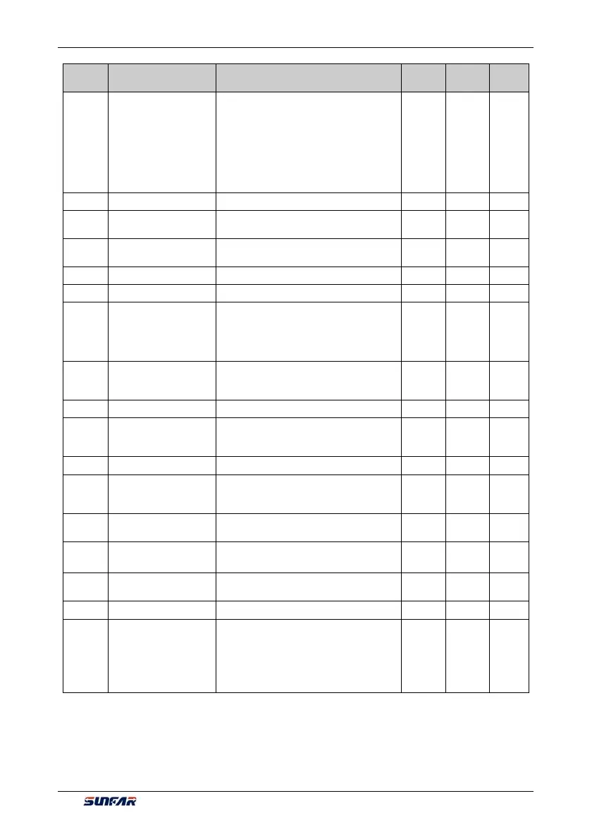
Function
Code
Name Setting Range and Description
Minimum
Unit
Factory
Default
Change
Limit
F0.4.38 Start/Stop Mode(H)
_ _ _ X: Start mode
0: Normal start
1: Revolution tracking start
_ _ X _: Reserved
_ X _ _: Stop mode
0: Deceleration stop
1: Free stop
1 0000 ×
F0.4.39 Start frequency 0.0~50.00Hz 0.01 0.50
F0.4.40
Start frequency holding
time
0.00~10.00Sec. 0.01 0.0
F0.4.41
Start pre-excitation
current
0.0~100.0(%) 0.1 35.0
F0.4.42 Start pre-excitation time 0.00~10.00Sec. 0.01 0.10
F0.4.43 Start delay 0.00~10.00Sec. 0.01 0.0
F0.4.44
DC band-type brake
control
_ _ _ X: DC band-type brake function
0: Closed
1: Open
_ _ X _: Reserved
1 0
F0.4.45
DC band type
brake/brake initial
frequency / speed
0.0~[F0.1.21] 0.01 2.00
F0.4.46 DC brake action time 0.0~10.00Sec. 0.01 0.0
F0.4.47
DC band-type
brake/brake injection
current
0.0~100.0(%) 0.1 50.0
F0.4.48 Restart after power-off 0: Forbidden 1: Effective 1 0
F0.4.49
Standby time for restart
after power-off/free
stop
0.1~10.0Sec. 0.1 0.5
F0.4.50
FWD and REV
transition dead time
0.00~5.00Sec. 0.01 0.00
F0.4.51
FWD and REV switch
mode
0: Switch at zero point
1: Start frequency switch
1 0
F0.4.52
Zero speed (frequency)
detection level
0.00~100.00Hz 0.01 0.10 Hz
F0.4.53 Zero speed delay time 0.00~10.00Sec. 0.01 0.05
F0.4.54
Emergency stop mode
(EMS)
0: The inverter will stop in deceleration
mode according to the emergency stop
and deceleration time.
1: The inverter will immediately lock output
and the motor will stop in free sliding
mode.
1 0