Example of Usage
V560 Series High Performance Closed-Loop Vector Inverter User manual
213
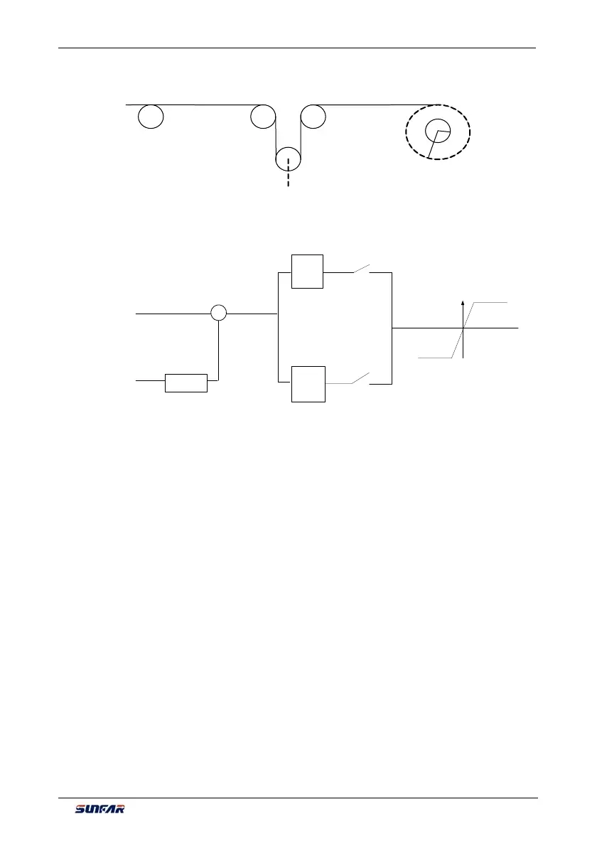
10.2.1 DIAGRAM OF CONSTANT TENSION CONTROL
10.2.2 DIAGRAM OF CONTROL STRUCTURE
PID
Tension feedback
Torque given
Select PID parameter
depending on tension
feedback value
Offset PID output
torque given
PID
Feedback
factor
+
-
Rotational speed
limiting
Deviation
Select PID parameter
depending on tension
feedback value
10.2.3 CONFIGURATION
1. F0.0.09= 0010 Closed-loop vector controlling mode
2. F8.3.39= 1
Take care, torque model
3. F8.3.40= 8
Torque channel selects offset PID output
4. F8.3.42= 1
Time of torque ascending: 1s
5. F8.3.43= 1
Time of torque descending: 1s
6. F8.3.45= 1500 Positive rotated speed limited set on the basis of motor’s actual rated
rotated speed
7. F8.3.46= 1500 Reverse rotated speed limited set on the basis of motor’s actual rated
rotated speed
8. F8.3.47= 0000
Torque limited channel setup
9. F8.3.48= -100
Smallest torque limited:-K*R*F/T*100% R: biggest semidiameter F: tension
value setting T: torque given T (rated torque of motor output) =9550*P/N,
N: rotated speed given 100 %< K<250%
10. F8.3.50= 100 Biggest torque limited= K*R*F/T*100%
11. F9.0.00= 0101 Input together of offset PID and frequency inverter Independent PID
12. F9.0.01= 100
Offset proportion: R*F/T (rated torque of motor output)*%
13. F9.0.02= 0010
Offset PID outputs bipolar positive deviation
14. F9.0.03= 20 Proportional gain of PID in first part (relatively bigger than parameter value in
second part)
15. F9.0.04= 2 Integral time of PID in first part (relatively smaller than parameter value in
Tension
feedback
R
R:radius of full plate
:radius of empty plate