Functional Parameter Table
V560 Series High Performance Closed-Loop Vector Inverter User Manual
70
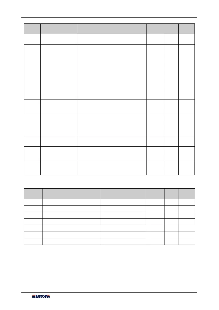
Function
Code
Name Setting Range and Description
Minimum
Unit
Factory
Default
Change
Limit
F7.0.20
Differential inertia
filtering time
0.01~100.00Sec. 0.01 10.00
F7.0.21
PID controller
characteristics
configuration
_ _ _ X: Deviation polarity
0: Positive deviation
1: Negative deviation (negation)
_ _ X _: Output polarity
0: Single polarity
1: Dual polarity (the symbol can be
reversed)
_ X _ _: Action when PID removed
0: PID control closed
1: PID output held up and current setting
status is maintained.
1 0000
F7.0.22
Permitted static
deviation (relative
100% setting)
0.0~20.0% 0.1 5.0
F7.0.23
PID output preset (at
the time of output
frequency as
compared to the upper
limiting frequency)
0.0~100.0 (%) 0.01 0.0
F7.0.24
Preset hold time
before PID starting
0.0~3600.0Sec. 0.1 0.0
F7.0.25
Actual sensor value
(range)corresponding
to 100% feedback
0.01~100.00 0.01 1.00
F7.0.26
Actual sensor value
corresponding to 0%
feedback
-100.00~100.00 0.01 0.0
6.2.32 PROCESS PID MULTI-STAGE SETTING
Function
Code
Name
Setting Range and
Description
Minimum
Unit
Factory
Default
Change
Limit
F7.1.27 Process PID multi-stage preset 1 -100.0~100.0 (%) 0.1 0.0
F7.1.28 Process PID multi-stage preset 2 -100.0~100.0 (%) 0.1 0.0
F7.1.29 Process PID multi-stage preset 3 -100.0~100.0 (%) 0.1 0.0
F7.1.30 Process PID multi-stage preset 4 -100.0~100.0 (%) 0.1 0.0
F7.1.31 Process PID multi-stage preset 5 -100.0~100.0 (%) 0.1 0.0
F7.1.32 Process PID multi-stage preset 6 -100.0~100.0 (%) 0.1 0.0
F7.1.33 Process PID multi-stage preset 7 -100.0~100.0 (%) 0.1 0.0