Description Of Specific Functions 143
V560 Series High Performance Closed-Loop Vector Inverter User Manual
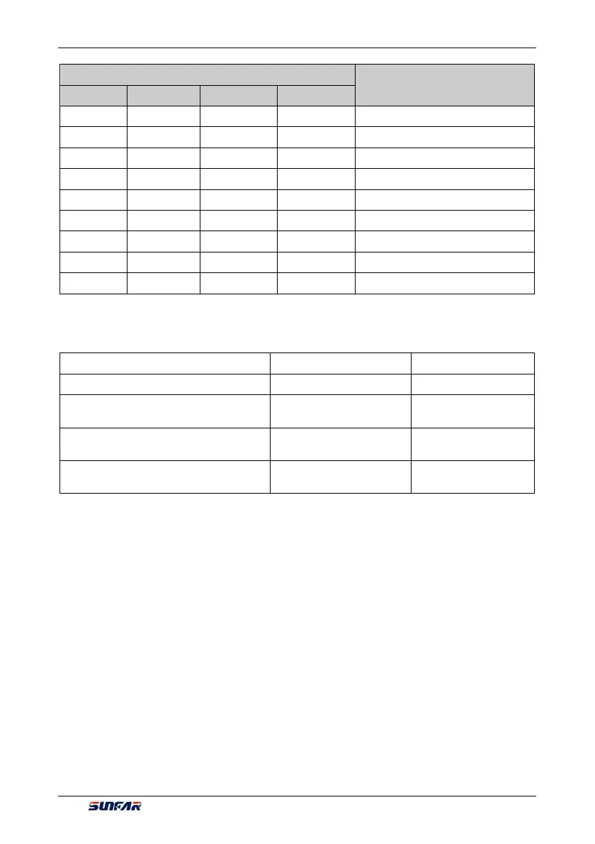
Binary number setting
Hexadecimal(digital show value)
BIT3 BIT2 BIT1 BIT0
0 1 1 1 7
1 0 0 0 8
1 0 0 1 9
1 0 1 0 A
1 0 1 1 b
1 1 0 0 C
1 1 0 1 d
1 1 1 0 E
1 1 1 1 F
7.14 MULTIFUNCTIONAL OUTPUT TERMINAL (GROUP F3.1)
F3.1.12 Multifunctional output DO1 Setting range: 0~71 Factory default: 1
F3.1.13 Multifunctional output DO2 Setting range: 0~71 Factory default: 2
F3.1.14 Multifunctional output DO3/
Fout/standard expansion card
Setting range: 0~71 Factory default: 63
F3.1.21 Multifunctional relay output
(RO1A/B/C)
Setting range: 0~71 Factory default: 4
F3.1.22 Multifunctional relay output
(RO2A/B/C)/standard expansion card
Setting range: 0~71 Factory default: 5
The control terminal D01-D03 is the on-off output terminal with programmable function, and its functions can
be defined by set values of F3.1.12-F3.1.14; Functions of output RO1and RO2 of relay, on-off output terminal
with programmable function, can be defined by set values of F3.1.21 and F3.1.22. Please refer to the
attached list for their set values and corresponding functions (Reference table of variables of multi-function
output terminal (DO/EDO/SDO).
1: Inverter running ready
When inverter is in normal running ready state, terminal will output effective signal/relay will pull in
(connection of TA and TC).
2: Inverter is running
When inverter is in running state, terminal will output effective signal/relay will pull in.
3: Equipment normal
When inverter is fault free, and DC busbar voltage is normal, terminal will effectively indicate signal/relay will
pull in.
4: Equipment fault
When inverter goes wrong and sends fault signal, terminal will output effective signal/relay will pull in.
5: Equipment alarm
When there is exception of inverter and sending warning signal, terminal will output effective signal/relay will