Description Of Specific Functions 147
V560 Series High Performance Closed-Loop Vector Inverter User Manual
F3.2.42 Max length count value Setting range: 10m~50000m Factory default: 50000
F3.2.43 Max liner speed Setting range: 0.01~500.00 Factory default: 10.00
When reach or exceed limit maximum accumulative length or linear speed, warning signal can be output
through multi-function output signal DOx.
F3.2.44 Current length count value Setting range: 0~50000m Factory default: ——
F3.2.45 Current liner speed Setting range: 0.0~500.00 Factory default: ——
Parameters in read-only state are used to display calculated results of current length and linear speed.
7.16 PULSE OUTPUT (GROUP F3.3)
F3.3.46 Type of output pulse signal
DO3/Fout
Setting range: 0, 1, 2 Factory default: 0
0: Frequency signal (0.25-100.00KHz)
1: Frequency signal
2: Pulse width modulation (PWM) signal
In setting 2, the fault frequency range is 0.25 ~100.00KHz, modulation frequency is set by maximum pulse
with outputting frequency parameter F3.3.48, which can be used to expand AO port.
F3.3.47 Min pulse output
frequency DO3/Fout
Setting range: 0.25~100.00KHz Factory default: 0.25
F3.3.48 Max pulse output
frequency DO3/Fout
Setting range: 0.25~100.00KHz Factory default: 10.0
When this group of parameters define multi-function output terminal DO3/Fout as pulse output (Function No.
63), its frequency range of output pulse, category settings of pulse signal output, and output frequency range
are different.
F3.3.50 Lower of limit
DO3/Fout
Setting range: 0.0~[F3.3.51] Factory default: 0.0
F3.3.51 Upper of limit
DO3/Fout
Setting range: [F3.3.51]~100.0% Factory default: 100.0
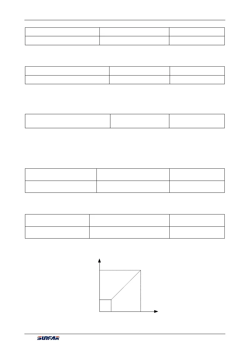
This group of parameters can determine the corresponding relationship between maximum, minimum
frequency and pulse output mapping variables, while the set values are the percentages of full pulse output
mapping variables. Corresponding relationship between the two is as shown in Figure 7-35:
[F3.3.48]
[F3.3.47]
Fout output frequency
[F3.3.50] [F3.3.51]
Per unit value of the pulse
output mapping variable
Figure 7-35 Characteristic curve of pulse output fount