232 EMC
V560 Series High Performance Closed-Loop Vector Inverter User manual
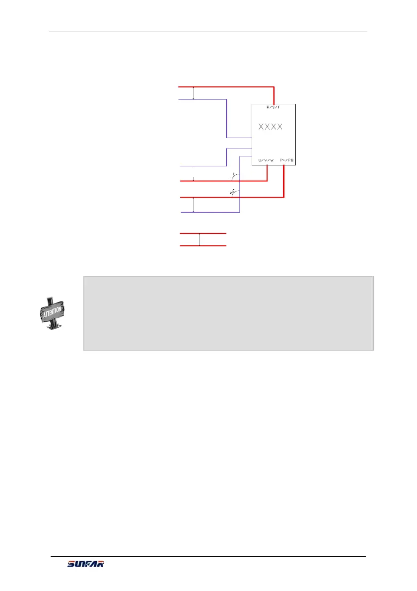
Wiring distance as below fig.
12.7 LEAKAGE CURRENT RESPONSE REQUIREMENTS
1) The output of inverter is high-speed pulse voltage, therefore it will generate high
frequency leakage current. To prevent electro shock and fire evoked by leakage
current, please install leakage circuit breaker for inverter.
2) The leakage current produced by inverter is relatively large, instant leakage current
of large power inverter may be tens of milliamperes, so inductive current of leakage
circuit breaker should be larger than 100mA.
3) High frequency pulse interference might cause leakage circuit breaker malfunction
under interference, please choose leakage circuit breaker with a high frequency
filter.
4) If to install several inverters, each inverter should have a leakage circuit breaker.
5) Factors that affect leakage current, as follows:
Control cable
Drive cable
Drive cable
Control cable
Control cable
Motor cable
Braking unit cable
Minimum 200mm
Motor cable
Minimum 500mm
Minimum 500mm
Minimum 300mm
Inverter
¾ In somewhere CE conformed or EMC radiation must be reduced, cable entry
should keep high frequency ground in 360 degree to restrain electro magnetic
interference. In addition, cable shield layer should connect with PE wire to
meet safety regulation.
¾ In floating or high ground (>30Ohms) power system, EMI filter cannot be
installed.