Accessories
V560 Series High Performance Closed-Loop Vector Inverter User Manual
234
13. ACCESSORIES
13.1 BRAKE ASSEMBLY
Operating principle: When the inverter drags the motor for acceleration and reversing, the voltage of the DC
bus inside the inverter may increase due to the motor's energy feedback. In order to prevent the inverter
from stopping as a result of over voltage protection, the brake unit will automatically connect to the energy
dissipation circuit before the voltage of the DC bus reaches the protection point. Hence the energy can be
released in the way of heat energy via the braking resistance, so as to prevent voltage rising continuously.
13.1.1 MODEL OF BRAKE UNIT
13.1.2 GUIDE OF BRAKE RESISTANCE SELECTION
Users are able to select resistance value and power according to actual needs, (but selected resistance
value cann’t be lower than recommended value in below table, while selected resistance power can be
bigger). Selection of brake resistance depends on motor generation power in system, and in concern with
system inertia, deceleration time, energy of potential energy load etc. The bigger system inertia, shorter
deceleration time and more frequent braking time, then to choose bigger power of brake resistance and
lower resistance value.
1 Resistance value selection
While braking, almost all motor regeneration energy consumes at braking resistance. The
formula:
U*U/R=Pb
U---- braking voltage under stable system braking state (it varies from different systems, it
takes 700V for common AC 380V system)
Pb----power of braking
2 Power of brake resistance selection
The power of brake resistance and power of braking keep consistent in theory, but should
take 70% derating into account. The formula:
0.7*Pr=Pb*D
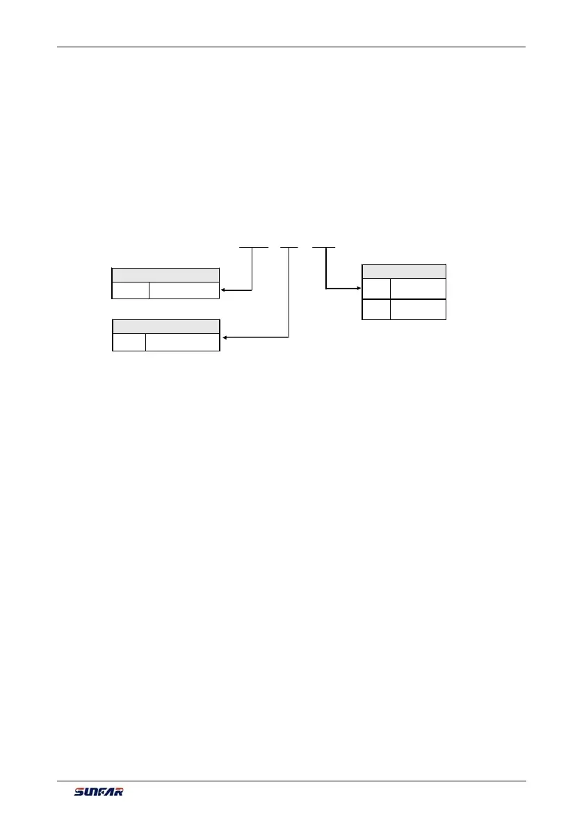
Product serial number
DBKU DC brake unit
Voltage class
4T 380V
Power class (KW )
0450 18 .5~45KW
0900 45 ~90 KW
DBKU – 4 T 0450
Figure 13-1 Sketch of model description