Description Of Specific Functions
V560 Series High Performance Closed-Loop Vector Inverter User Manual
184
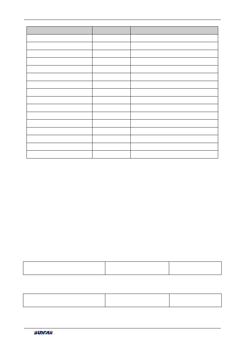
Register Name Access address Remarks
Mapping application parameter 2 0x1304 The access parameter is set by FA.1.09.
Mapping application parameter 3 0x1305 The access parameter is set by FA.1.10
Mapping application parameter 4 0x1306 The access parameter is set by FA.1.11.
Mapping application parameter 5 0x1307 The access parameter is set by FA.1.12.
Mapping application parameter 6 0x1308 The access parameter is set by FA.1.13.
Status word 0x1309 Can be read as per the discrete quantity (1~16)
Mapping status parameter 1 0x130A The access parameter is set by FA.1.14.
Mapping status parameter 2 0x130B The access parameter is set by FA.1.15.
Mapping status parameter 3 0x130C The access parameter is set by FA.1.16.
Mapping status parameter 4 0x130D The access parameter is set by FA.1.17.
Mapping status parameter 5 0x130E The access parameter is set by FA.1.18.
Mapping status parameter 6 0x130F The access parameter is set by FA.1.19.
Mapping status parameter 7 0x1310 The access parameter is set by FA.1.20.
Mapping status parameter 8 0x1311 The access parameter is set by FA.1.21.
Mapping status parameter 9 0x1312 The access parameter is set by FA.1.22.
Mapping status parameter 10 0x1313 The access parameter is set by FA.1.23.
The mapping parameters are determined by FA.1 group of parameters.
For example, in one frame of standard MODBUS protocol data, it’s impossible to read the status parameters
d0.0.02, d0.0.05, d1.0.01 and d1.1.31 and status word once and for all with a common method. To map
status parameters into the bus-controlled parameter area with continuous address, set with the following
method:
[FA.1.14] = d0.02
[FA.1.15] = d0.05
[FA.1.16] = d1.01
[FA.1.17] = d1.31
Then you it just needs to read the data in the continuous address 0x130A ~ 0x130D.
7.40 COMMUNICATION LINKAGE SYNCHRONOUS CONTROL
(GROUP FA.2)
FA.2.26 Linkage setting proportion
coefficient
Setting Range: 0.010~10.000 Factory Default: 1.000
During linkage control, this parameter defines the proportion between the output frequency of the master
machine and the slave machine; the parameter of the master inverter does not function.
FA.2.27 Coupling fine proportion
adjustment
Setting range: 0~3 Factory default: 0
0: No fine adjustment
If the fine adjustment source for linkage proportion coefficient is void, then: Slave frequency command =