Operation And Simple Running Of Frequency Inverter
V560 Series High Performance Closed-Loop Vector Inverter User Manual
42
Press key to stop operation and cut off the power supply.
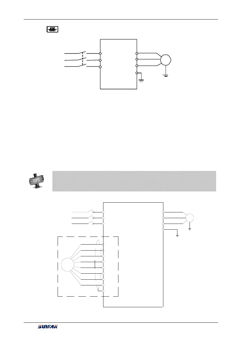
5.3.3.2 VC (INDUCTIVE VECTOR) OPERATION
The following parameters also need to be set except the above set parameters required by SVC operation.
The wiring diagram is as shown in Figure 5-4.
[F0.0.09]=0010 (inductive vector control)
[F8.0.04]=0 (speed feedback channel)
[F8.0.05]=1000 (pulse of encoder per revolution)
[F8.0.06] if F/R periodic vibration is occurred in starting, this parameter shall be set as 1 (or exchange the
wiring of A, B pulse) other operations are the same as that of SVC operation.
¾ If the motor is completely empty-load, slight oscillation may occur sometimes in the
operation under high carrier frequency. At this time, please reduce the setting value of the
carrier fre
uenc
.
Parameter
F1.1.13
.
M
Motor
U
W
V
R
S
T
Three-phase
power supply
×
×
×
Three-phase
breaker
Grounding
E
Figure 5-3 Wiring for the operation of SVC mode
E
+12V
GD
A+
A-
B+
B-
C+
C-
PG
V560
Grounding
Motor
M
V
W
PG expansion card
(match)
Three-phase
breaker
Three-phase
power supply
U
E
R
S
T
Figure 5-4 Wiring for the operation of VC mode