Functional Parameter Table
V560 Series High Performance Closed-Loop Vector Inverter User Manual
48
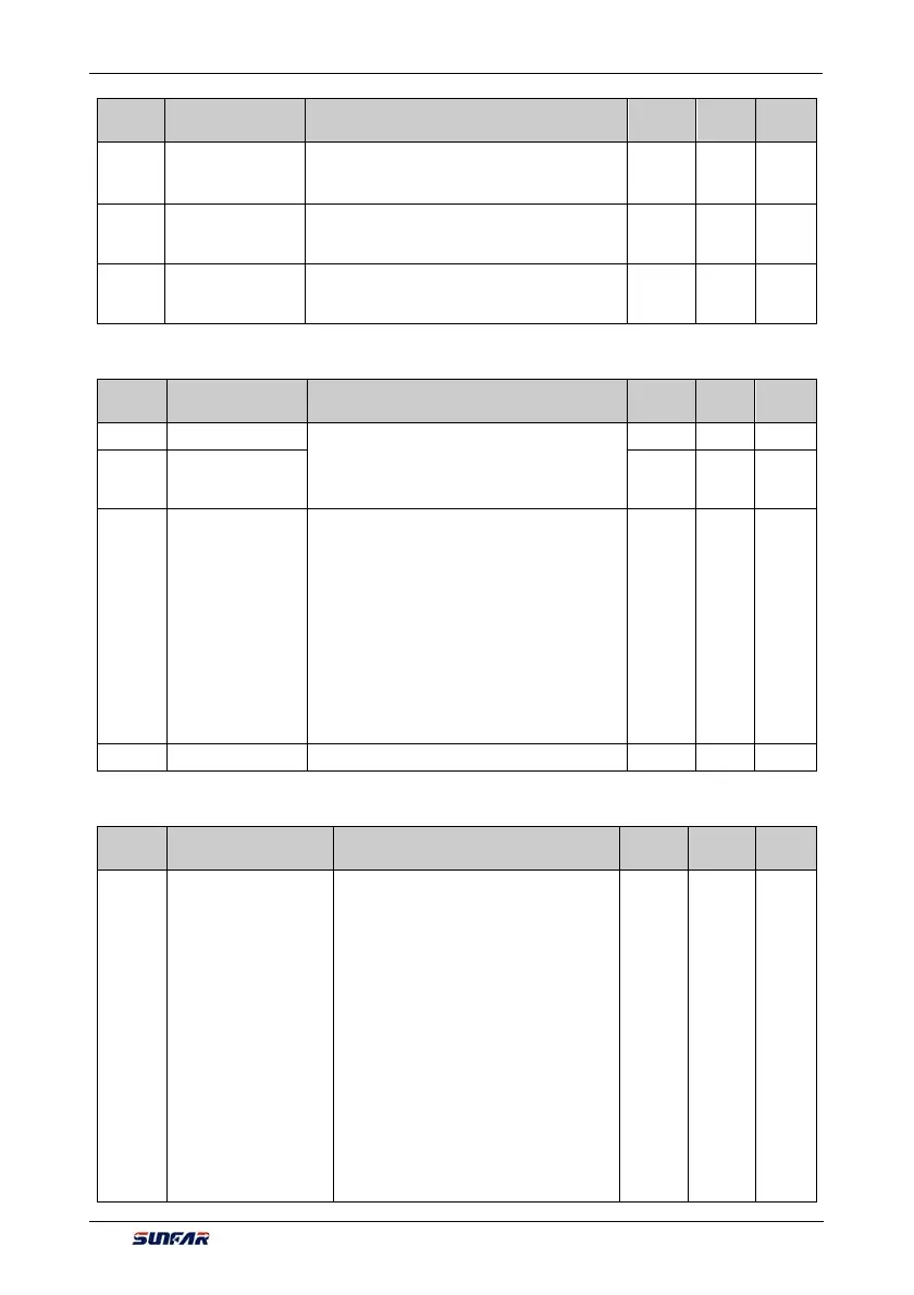
Function
Code
Name Setting Range and Description
Minimum
Unit
Factory
Default
Change
Limit
F0.2.30
Minimum value of
frequency setting
source 2
0.0~[F0.2.31] 0.01 0.0
F0.2.31
Maximum value of
frequency setting
source 2
[F0.2.30]~[F0.2.20] 0.01 50.0
F0.2.32
Panel digital set
value of frequency
setting source 2
0.0~[F0.2.31] 0.01 0.0
6.2.4 CONTROL COMMAND SOURCE
Function
Code
Name Setting Range and Description
Minimum
Unit
Factory
Default
Change
Limit
F0.3.33 Control command 1 0: Operating panel
1: External control terminal
2: MODBUS fieldbus /standard expansion card
configuration
1 0
F0.3.34 Control command 2 1 0
F0.3.35
External control
terminal action
mode (H)
_ _ _ X: Control command
0: 2 wire mode 1
1: 2 wire mode 2
2: 3 wire mode 1
3: 3 wire mode 2
_ _ X _: Command power-on first starting
0: Running signal level starting
1: Running signal rising edge starting
(2 wire mode 1 and 2)
_ X _ _: Reserved
X _ _ _: Reserved
1 0000 ×
F0.3.36 Reserve
6.2.5 START AND STOP
Function
Code
Name Setting Range and Description
Minimum
Unit
Factory
Default
Change
Limit
F0.4.37
Start/Running
permission(H)
LED _ _ _ X: Start permission
0: Function closed
1: Permitted when the multifunctional
terminal is effective (Function No. 42)
2: Command word from standard fieldbus
(standard expansion card)
LED _ _ X _: Reserved
LED _ X _ _: Running permission
0: Function closed
1: Permitted when the multifunctional
terminal is effective (Function No. 43)
2: Command word from standard fieldbus
(standard expansion card)
LED X _ _ _: The action mode when the
running permission signal is void
0: Free stop
1: Deceleration stop
1 0000 ×