128 Description Of Specific Functions
V560 Series High Performance Closed-Loop Vector Inverter User Manual
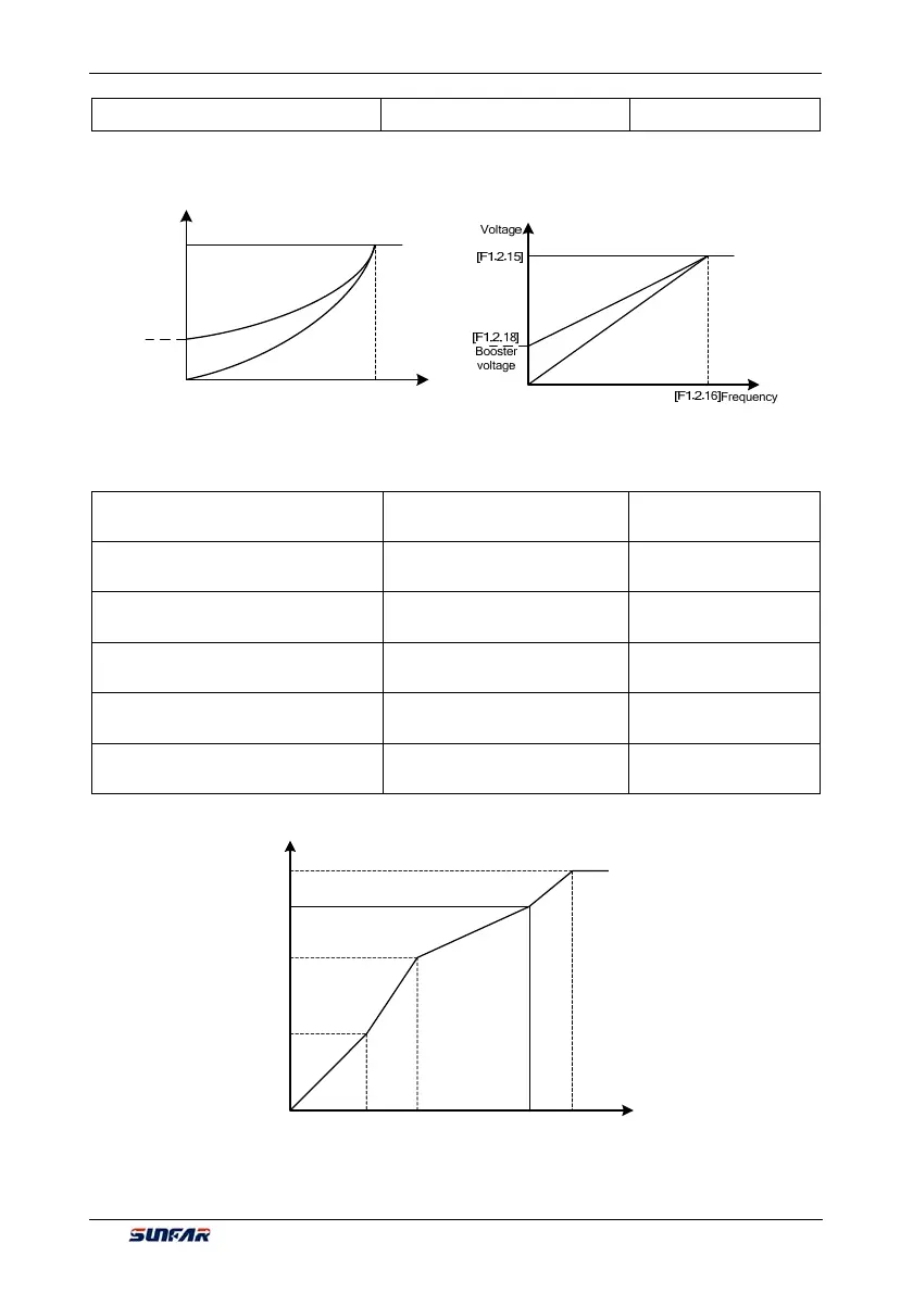
F1.2.18 Torque boost motor 1 Setting range: 0.0~20.0% Factory default: ☆
It is used to improve the inverter’s low frequency torque characteristics. When the inverter runs at low
frequency, it will make compensation for the inverter's output voltage. Its set value is the percentage relative
to the motor’s reference voltage [F1.2.16]. See Figure 7-27-A and Figure 7-27-B.
Fre
uenc
Voltage
[F1.2.16]
[F1.2.18]
Booster
voltage
[F1.2.15]
F1.2.19 V/F curve 1
st
frequency
motor 1
Setting range: 0.0~[F0.1.21] Factory default: 0.0
F1.2.20 V/F curve 1
st
voltage of
motor 1
Setting range: 0~500V Factory default: 0.0
F1.2.21 V/F curve 2
nd
frequency
motor 1
Setting range: 0.0~[F0.1.21] Factory default: 0.0
F1.2.22 V/F curve 2
nd
voltage of
motor 1
Setting range: 0~500V Factory default: 0.0
F1.2.23 V/F curve 3
rd
frequency
motor 1
Setting range: 0.0~[F0.1.21] Factory default: 0.0
F1.2.24 V/F curve 3
rd
voltage of
motor 1
Setting range: 0~500V Factory default: 0.0
This group of parameters is used to flexibly set V/F curve desired by users, as shown in Figure 7-28.
Voltage
Frequency Hz
[F1.2.16]
[F1.2.24]
[F1.2.22]
[F1.2.20]
[F1.2.19] [F1.2.21] [F1.2.23] [F1.2.15]
Figure 7-27-A Sketch of torque
booster for descendin
tor
ue curve
Figure 7-28 V/F customized curve
Figure 7-27-B Sketch of torque
booster for constant torque curve