Functional Parameter Table
V560 Series High Performance Closed-Loop Vector Inverter User Manual
76
Function
Code
Name Setting Range and Description
Minimum
Unit
Factory
Default
Change
Limit
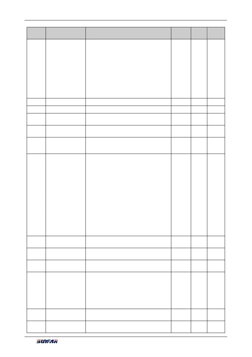
F9.0.02
Compensation PID
controller feature
configuration
_ _ _ X: Deviation polarity
0: Positive deviation
1: Negative deviation (negation)
_ _ X _: Output polarity
0: Single polarity
1: Dual polarity
_ X _ _:Loss of signal response
0: PID control closed
1: PID output held on (maintaining current
running setting)
1 0010
F9.0.03 Proportional gain 1 0.0~100.00 0.01 2.00
F9.0.04 Integration time 1 0.0, 0.01~100.00Sec. 0.01 2.00
F9.0.05
Differential
coefficient 1
0.0, 0.01~10.00 0.01 0.0
F9.0.06
Differential inertia
filtering time 1
0.01~25.00Sec. 0.01 5.00
F9.0.07
Compensation PID
output inertia filtering
time coefficient1
0.0, 0.01 ~ 20.00Sec. 0.01 1.00
F9.0.08
Selection of
compensation PID
set value
0: Internal digital setting (F9.0.11)
(auto save after power off)
1: Panel shuttle potentiometer preset value
2: Analog input AI1
3: Analog input AI2
4: Analog input AI3
5: UP/DW terminal (clear after stop)
6: UP/DW terminal (maintaining after stop and
save after power-off)
7: MODBUS Fieldbus set value 1
8: MODBUS Fieldbus set value 2
9: Expansion communication set 1
10: Expansion communication set 1
1 0
F9.0.09
Analog input
minimum value
0.0V~[F9.0.10]/AI2: 0.0mA~[F9.0.10] 0.01 0.0
F9.0.10
Analog input
maximum value
[F9.0.09]~10.00/AI2: [F9.0.09]~20.00mA 0.01 10.00
F9.0.11
PID internal
reference
0.0~100.0 (%) 0.1 0.0
F9.0.12
Selection of
compensation PID
feedback value
0: Analog input AI1
1: Analog input AI2
2: Analog input AI3
3: Output current
4: Output torque
5: Output power
1 0
F9.0.13
Actual value analog
input minimum
0.0V~[F9.0.14]/AI2: 0.0mA~[F9.0.14] 0.01 0.0
F9.0.14
Actual value analog
input maximum
[F9.0.13]~10.00/AI2: [F9.0.13]~20.00mA 0.01 10.00