150 Description Of Specific Functions
V560 Series High Performance Closed-Loop Vector Inverter User Manual
F4.2.26 AO1 lower limit scaling Setting range: 0.0~[F4.2.27] Factory default: 0.0
F4.2.27 AO1 upper limit scaling
Setting range:
[F4.2.26]~100.0%
Factory default: 100.0
F4.2.32 AO2 lower limit sacling
/standard expansion card
Setting range: 0.0~[F4.2.33] Factory default: 0.0
F4.2.33 AO2 upper limit scaling
/standard expansion card
Setting range:
[F4.2.32]~100.0%
Factory default: 100.0
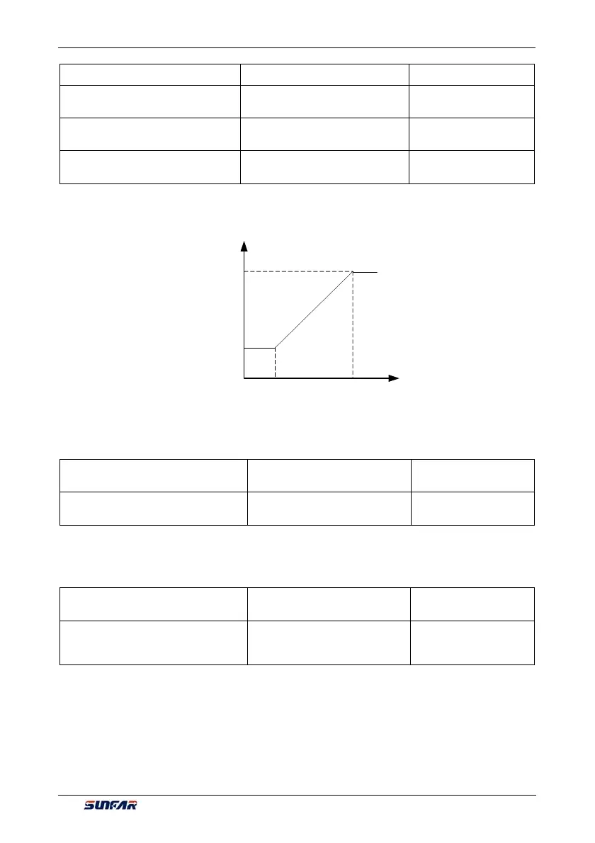
Corresponding relationship between maximum and minimum of AO1, AO2 output given by this group of
parameters and mapping variable (see figure below), whose set value is the percentage relevant to the full
output of mapping variable of AO1, AO2.
F4.2.28 AO1 filtering time
constant
Setting range: 0.01~10.00Sec. Factory default: 0.10
F4.2.34 AO2 filtering time
constant/standard expansion card
Setting range: 0.01~10.00Sec. Factory default: 0.10
This group of parameters is used to set the filtering time coefficient of AOI, AO2 analog output signal,
according to selection of requirements of the rapidity and wave character of signal. The larger the time
coefficient is, the smoother the output signal is, and the slower the response is.
F4.2.29 AO1 output signal
selection
Setting range: 0.00~20.00mA
(0.00~10.00V)
Factory default: 0.0
F4.2.35 AO2 output signal
selection/standard expansion
card
Setting range: 0.00~20.00mA
(0.00~10.00V)
Factory default: 0.0
When the mapping variable of multifunction analog output AO1, AO2 is a fixed value (F4.02.22, F4.2.23 is
set as 24), fixed value of AO1 output is [F4.2.29], and the fixed value of AO2 output is [F4.2.35], which can
output voltage and current signal.
AO output voltage
AO assignment
upper lower limit
Per unit value
of AO mapping
variable
AO assignment
upper limit
AO minimum
AO maximum
Figure 7-39 AO output characteristic curve