EasyManua.ls Logo

Svantek SVAN 958A - Page 185

Svantek SVAN 958A
306 pages
Print Icon
To Next Page IconTo Next Page
To Previous Page IconTo Previous Page
Loading...
185
SVAN 958A User Manual
Linear operating ranges for LEQ measurements with the Free Field compensation
Two measuring ranges are available: Low and High.
The starting point at which tests of level linearity shall begin is 94.0 dB for the frequencies specifies below. For
the Low measurement range and A weighting linearity test at 31.5 Hz, the starting point is 69 dB.
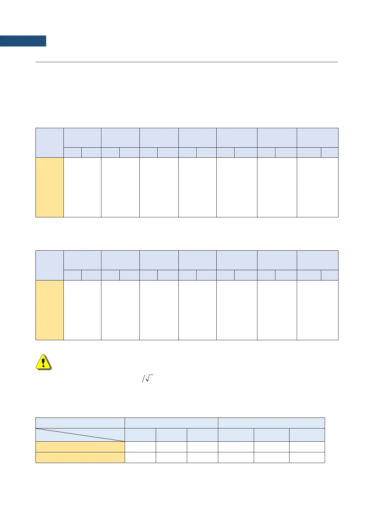
Table C.1.1. Linear operating ranges for the Free Field filter and Low measurement range (for the
sinusoidal signal and microphone sensitivity 50 mV/Pa)
[dB]
L
AS/F
L
CS/F
L
LINS/F
L
AeqT
L
CeqT
L
AE
L
Cpeak
(t
int
= 2 s)
from
to
from
to
from
to
from
to
from
to
from
to
from
to
31.5 Hz
24
75
24
112
30
115
24
75
24
112
27
78
50
115
500 Hz
24
115
24
115
30
115
24
115
24
115
27
118
50
118
1 kHz
24
116
24
114
30
115
24
116
24
114
27
119
50
117
4 kHz
24
114
24
112
30
115
24
114
24
112
27
117
50
115
8 kHz
24
110
24
109
30
115
24
110
24
109
27
113
50
112
12.5 kHz
24
75
24
112
30
115
24
75
24
112
27
78
50
115
Table C.1.2. Linear operating ranges for the Free Field filter and High measurement range (primary) (for
the sinusoidal signal and microphone sensitivity 50 mV/Pa)
[dB]
L
AS/F
L
CS/F
L
LINS/F
L
AeqT
L
CeqT
L
AE
L
Cpeak
(t
int
= 2 s)
from
to
from
to
from
to
from
to
from
to
from
to
from
to
31.5 Hz
44
97
44
134
46
137
44
97
44
134
47
100
70
137
500 Hz
44
137
44
137
46
137
44
137
44
137
47
140
70
140
1 kHz
44
138
44
136
46
137
44
138
44
136
47
141
70
139
4 kHz
44
136
44
134
46
137
44
136
44
134
47
139
70
137
8 kHz
44
132
44
131
46
137
44
132
44
131
47
135
70
134
12.5 kHz
44
97
44
134
46
137
44
97
44
134
47
100
70
137
Note: For the signals with the crest factor n > 1.41 upper measuring range of the RMS
(LEQ) is reduced. The valid upper limit can be calculated according to the below given formula:
, where A is the upper limit for the sinusoidal signal
Example: For the crest factor n = 10 the upper limit is A
10
= 120 dB.
Table C.1.3. Self-generated noise for different weighting filters
Electrical *)
Acoustical compensated
Weighting filter
Range
A
C
LIN
A
C
LIN
Low
< 13 dB
< 13 dB
< 19 dB
< 17 dB
< 17 dB
< 23 dB
High
< 33 dB
< 33 dB
< 35 dB
< 37 dB
< 37 dB
< 39 dB
*) measured with the ST 02 microphone equivalent impedance 18 pF ± 10%
( )
2log20137 nA
n
=

Table of Contents

Related product manuals