4 MEASUREMENT PARAMETERS SETTING – Input
The Input list contains the elements, which
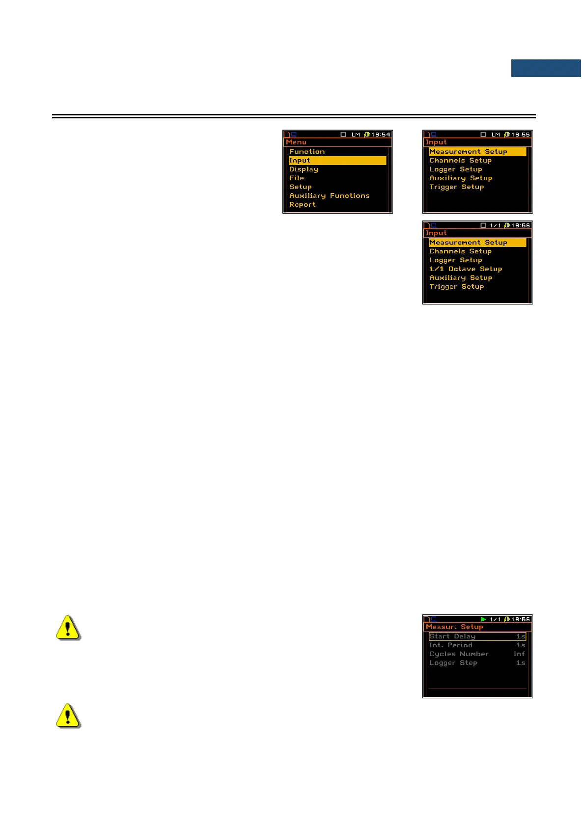
enable the user to programme the
measurement parameters for all channels and
profiles. The Input list appears after pressing
the <Menu> key, selecting the Input text and
pressing <ENTER>.
The Input list content depends on the function selected in the
Measurement Function list and some additional positions appears if
1/1 Octave, 1/3 Octave, Dosimeter, FFT or RT60 are selected respectively:
1/1 Octave Setup, 1/3 Octave Setup, Dosimeter Setup, FFT Setup or
RT60 Setup.
The Input list consists of:
Measurement Setup enables the user to select the general measurement parameters for all
channels;
Channels Setup enables the user to program the individual parameters for channels;
Logger Setup enables the user to program the logger functions – measurements logging and
signal recording;
1/1 Octave Setup enables the user to set the parameters of the 1/1 octave analysis. Position
appears only when the 1/1 Octave function is selected;
1/3 Octave Setup enables the user to set the parameters of the 1/3 octave analysis. Position
appears only when the 1/3 Octave function is selected;
FFT Setup enables the user to set the parameters of the FFT analysis. Position appears
only when the FFT function is selected;
Cross Spectrum Setup enables the user to set the parameters of the cross-spectrum measurement.
Position appears only when the Cross Spectrum function is selected;
Intensity Setup enables the user to set the parameters of the sound intensity measurement.
Position appears only when the Sound Intensity function is selected;
RT60 Results enables the user to set the parameters of the reverberation time measurement.
Position appears only when the RT60 function is selected;
Dosimeter Setup enables the user to set the parameters of the dosimeter function. Position
appears only when the Dosimeter function is selected;
Wave Parameters enables the user to set the parameters of the signal recording. Position
appears only when the Wave Recorder function is selected;
Auxiliary Setup enables the user to program auxiliary instrument functions;
Trigger Setup enables the user to set the parameters of measure trigger.
Note: Any parameter in the lists of the Input menu can be changed
only when the instrument is not making a measurement. The
parameters are displayed in a frame and any change of it is
impossible. The “play” icon in the top line indicates that the
instrument is performing the measurements.
Note: The vibration parameters can be presented in Logarithmic (decibels) or Linear (m/s
2
) units.
It depends on the Display Scale position value (path: <Menu> / Display / Display Setup / Channel
x / Display Scale), e.g. 10 m/s
2
can be presented as 140 dB.