2.1 INPUT AND OUTPUT SOCKETS OF THE INSTRUMENT
Top cover of the instrument
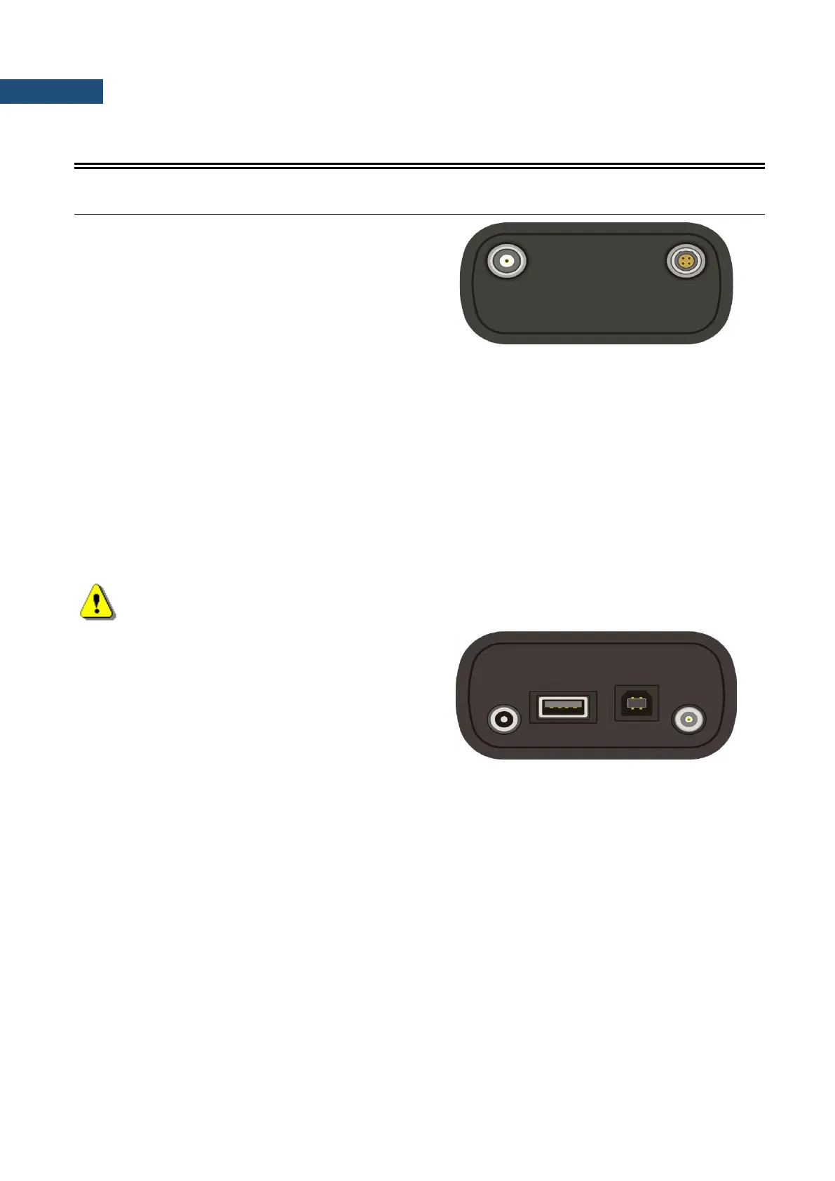
The measurement inputs are placed on the top cover of
the instrument: 4-pins Lemo compatible socket type
ENB.0B.304 for Channels 1–3 and TNC for Channel 4,
all with IEPE power supply for the accelerometers or
microphone preamplifiers.
The microphone preamplifier SV 12L has the proper plug-in with the screw for direct connection with the
instrument to the TNC connector (Channel 4) but it is recommended to use the preamplifier
with any of the extension cables (i.e. SC 26) or the SA 08 gooseneck. The same type of the connector should
be used to attach one-channel accelerometer to Channel 4. The SC 27 coiled cable
is recommended in this case. In order to connect the SV 12L microphone preamplifier to Channels 1–3 the
user has to use the SC 49 cable (LEMO 4-pins plug to 3 * TNC sockets, 0.7 meters long). The SC 49
or SC 39P (LEMO 4-pins plug to 3 * BNC sockets, 0.7 meters long) cables should be used to connect one-
channel accelerometer to any of the Channels 1–3. The triaxial accelerometers can be easy connected to
Channels 1–3 by means of the SC 38 cable (4-pins Microtech to LEMO 4-pins, 2.7 meters long). It is
recommended to attach the SV 25 dosimeter microphone with the integrated preamplifier
and a cable to Channel 4.
The full description of the signals connected to the sockets is given in the Appendix C.
Note: Pay attention that the TNC connector should be always twisted to the light resistance but the
LEMO connector is a push-pull only.
Bottom cover of the instrument
In the bottom cover there are four sockets, placed from
the right to the left as follows: Ext. Pow., USB Host,
USB Device and I/O.
The USB 1.1 Client interface (the USB Device socket) is the serial interface working with 12 MHz clock. Thanks
to its speed, this interface is widely used in all PCs. In the instrument, the standard 4-pins socket is used
described in details in Appendix C.
The USB Host 1.1 interface can be used to connect the external storage, enabling the device
to register virtually infinite sequence of measurement results.
The Ext. Pow. socket located on the bottom cover of the instrument is Marushin MJ-14 compatible socket,
dedicated for the standard Φ 5.5 / 2.1 mm plug (the right one in the Fig. above). The user can connect the
external mains adapter (110 V / 230 V) which furnishes the proper DC level. The instrument can be charged
from the external DC source (6 V / 500 mA DC ÷ 15 V / 250 mA DC). The current consumption depends on the
voltage of the power supplier.
The additional input / output socket, called I/O, is 1-pin LEMO compatible socket type ERN.00.250 (the left one
in the Fig. above). The function of this socket can be selected from menu (path: <Menu> / Setup /
EXT. I/O Setup / Mode). The socket can be used as: