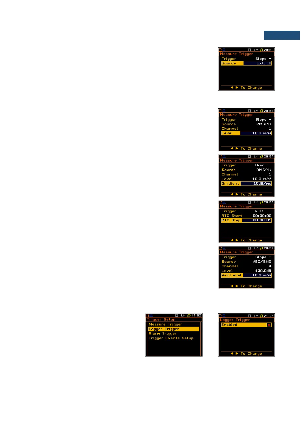
Selection of the triggering signal
In the Source position four options are available: RMS(1), Ext. IO (in case of
Slope + and Slope –), VEC/SND, Vector.
In case of Grad + mode only the output signal from the RMS detector coming
from the first profile of the selected channel can be used as a source of
triggering signal (RMS(1)).
In case of Slope + and Slope – as a source of the triggering signal can be used
the signal connected to the extended input/output socked named Ext. IO .
Selection of channel for triggering condition
In the Channel position the user can select the channel of triggering signal.
Setting the level of the triggering signal
The level of the triggering signal (Level) can be set in the range 24 dB to
136 dB for acoustic signals or from 1 mm/s
2
to 10.0 km/s
2
for vibration signals.
Setting the speed of the triggering signal changes
The speed of the triggering signal changes (Gradient) can be set in the range
of 1 dB/ms to 100 dB/ms.
Setting the start time of triggered measurement
The measurement can be triggered with the time selected in RTC Start.
Time-triggered measurement can be repeated with the step selected in the
RTC Step. The number of repetition is the number of cycles set in the
Cycles Number (path: <Menu> / Input / Measurement Setup).
In case the VEC/SND is selected as a trigger Source the Vec.Level position
defines the level of the triggering source.
4.5.2 Logger trigger setup – Logger Trigger
The Logger Trigger switches on the result
logging.
The Logger Trigger parameters define the
way the measurement results are saved in the
logger.