Model 4200A-SCS Prober and External Instrument Control Section 6: Using a Model 82 C-V System
4200A-913-01 Rev. A December 2020 6-33
Enable or disable the analog filter; see Details:
▪ Disable the filter: 0
▪ Enable the filter: 1
The complete name and path for the cable compensation file; see Details
Enable or disable an offset correction measurement:
▪ Disable offset correction: 0
▪ Enable offset correction: 1
KCon instrument ID; default is CMTR1; can be CMTR1 to CMTR4, depending on your
system configuration
The DUT pin to which the 5951 input terminal is attached (−1 to 72); if a value of
less than 1 is specified, no switch matrix connections are made; see Details
The DUT pin to which the 5951 output terminal is attached (−1 to 72); if a value of
less than 1 is specified, no switch matrix connections are made; see Details
Output; the measured array of high frequency capacitance values
Output; the array of measured conductance (G) or resistance (R) values
Output; the array of time from the 595 output for each measurement step
Details
This method can be used for minority carrier lifetime measurements using Zerbst plot.
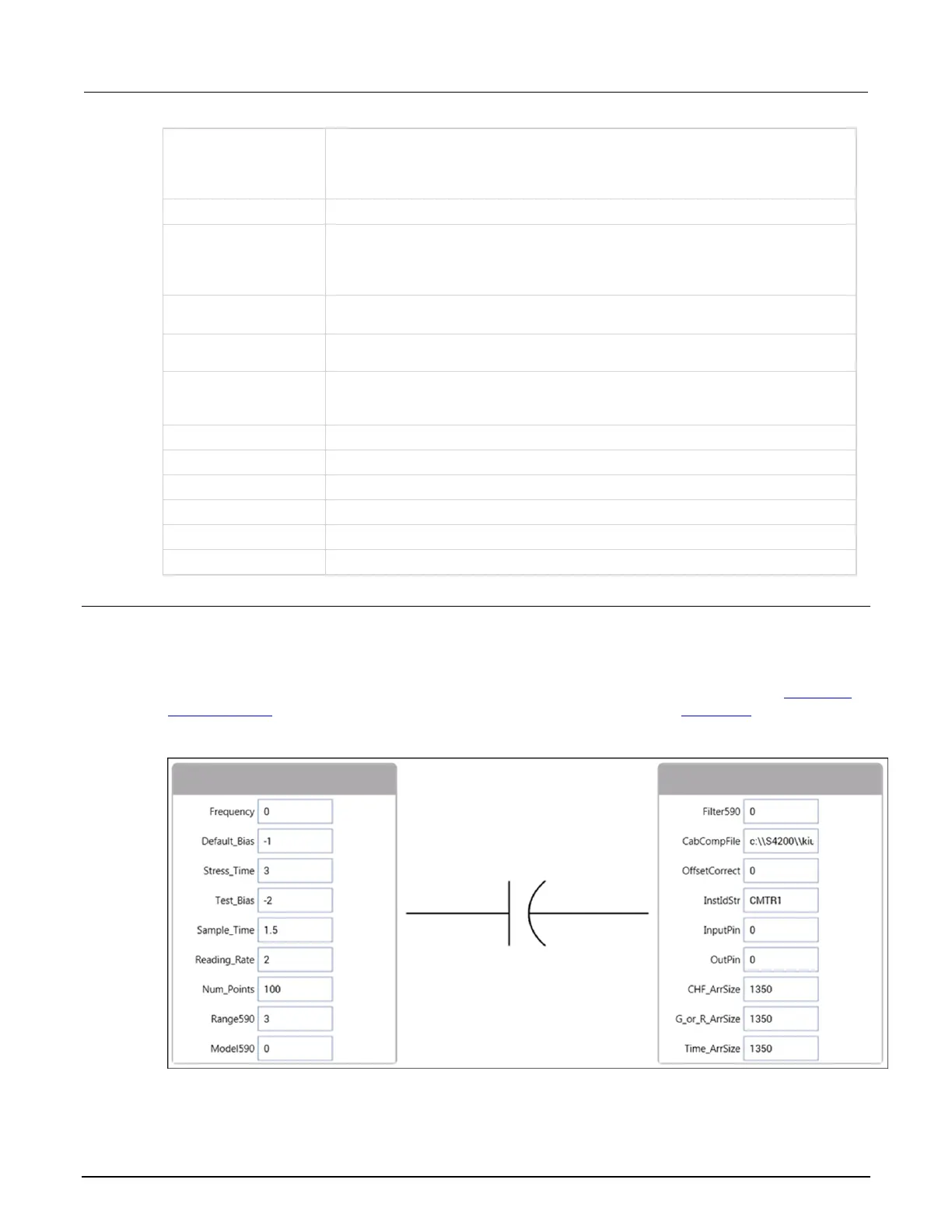
The figure below shows the default parameters for the ctsweep UTM, which uses the CtSweep82
user module. In this example, the Model 82 is set to first stress the DUT at +3 V for three seconds,
and then perform 100 capacitance measurements at −3 V using a 0.1 s time interval (see CtSweep
test description (on page 6-19)). For details on C-t measurements, refer to C-t sweep (on page 6-18).
Figure 105: CtSweep82 user module

 Loading...


