4: INSTALLATION
10. Identify the 9-pin connector that's pre-installed in the
electrical cabinet's wiring harness. Connect it to the A-
axis driver.
Figure 4-205: 9-pin connector connected to the A-axis
driver.
11. Identify the 15-pin I/Oadapter provided with this kit.
Connect it to the A-axis driver with both screws and a 1.5
mm hex wrench.
Figure 4-206: 15-pin I/O adapter connected to the A-
axis driver.
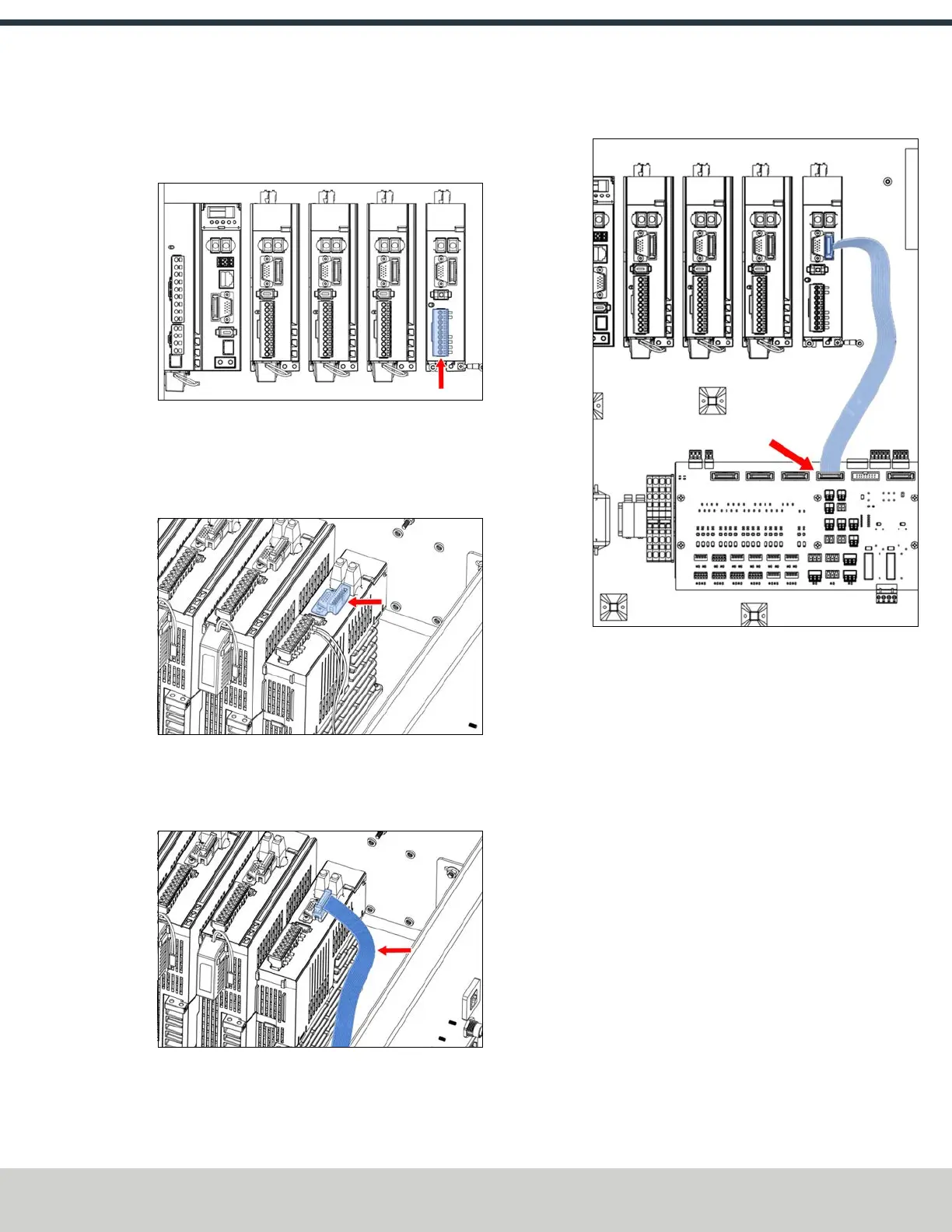
12. Identify the IDCribbon cable that's included in this kit.
Connect one end to the A-axis driver.
Figure 4-207: IDCribbon cable connected to the A-axis
driver.
13. Connect the loose end of the IDCribbon cable to the IDC
header on the machine control board.
Figure 4-208: IDC ribbon cable connected to the
machine control board.
14. On the top right panel of the enclosure, identify the A-
Axis Motor and A-Axis Encoder knockout holes. Use a
hammer and punch to remove the knockouts.
15. Identify the motor and encoder cables, which are
shipped connected to the microARC itself. Disconnect
them.
©Tormach® 2024
Specifications subject to change without notice.
Page 95 UM10811: 1500MX Operator's Manual (Version 0424A)
For the most recent version, see tormach.com/support
 Loading...


