16. Remove the nut from the bulkhead connector for the
power cable (the cable with the 4-pin connector). Put it
in the A-Axis Motor hole, and thread the nut onto the
bottom from inside the enclosure. Repeat this step to
secure the encoder bulkhead into the top panel.
Figure 4-209: A-axis motor and encoder cables routed
through the enclosure's knockout holes.
17. Route the loose end of the power and encoder cable
through the channel on the top of the enclosure, and
toward the electrical cabinet.
18. Identify the cable gland plate on the top right of the
electrical cabinet. Loosen the four nuts that secure it to
the cabinet, insert the encoder and power cables through
the cable gland plate, and tighten the four nuts.
Figure 4-210: Cable gland plate screws.
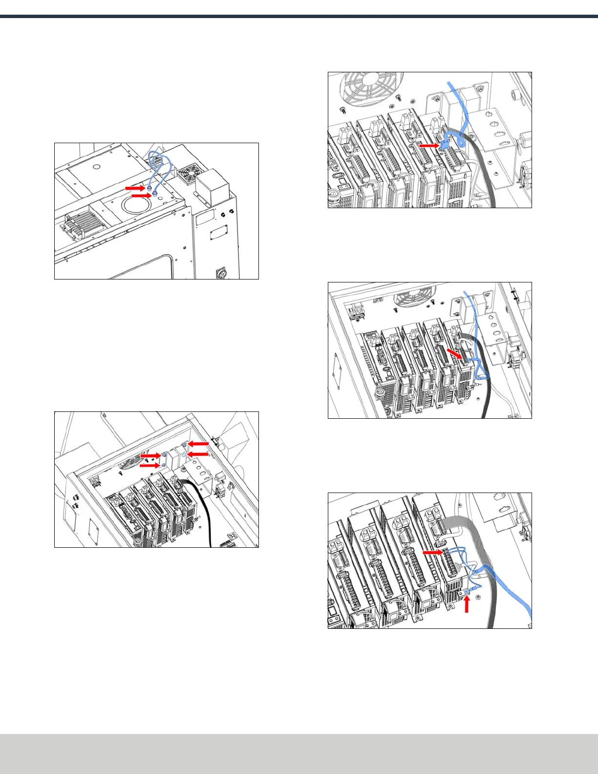
19. Connect the IEEE 1394 cable from the encoder to the A-
axis driver.
Figure 4-211: A-axis encoder cable connected to the
A-axis driver.
20. On the 9-pin connector that you previously connected to
the A-axis driver, connect the four motor power cables to
the A-axis driver according to their labels (U, W, V, PE).
Figure 4-212: A-axis motor power wires connected to
the A-axis driver.
21. Identify the ground cable that you set aside previously.
Connect it to the A-axis driver and tighten the Phillips
screw.
Figure 4-213: Ground wires connected to the A-axis
driver.
©Tormach® 2024
Specifications subject to change without notice.
Page 96 UM10811: 1500MX Operator's Manual (Version 0424A)
For the most recent version, see tormach.com/support
4: INSTALLATION
 Loading...


