4. Connect the wires Power (gray) to TO0 (blue) and Ground (red) to TO1 (pink).
NOTICE
Once the robot makes an Emergency Stop, the voltage is set to 0V for both Power
Pins (power is off).
Tool Digital Outputs
Digital Outputs support three different modes:
Mode Active Inactive
Sinking (NPN) Low Open
Sourcing (PNP) High Open
Push / Pull High Low
Access Tool I/O in the Installation Tab (see partPart II PolyScope Manual) to configure the output
mode of each pin. The electrical specifications are shown below:
NOTICE
Once the robot makes an Emergency Stop, the Digital Outputs (DO0 and DO1) are
deactivated (High Z).
CAUTION
The Digital Outputs in the tool are not current-limited. Overriding the specified data
can cause permanent damage.
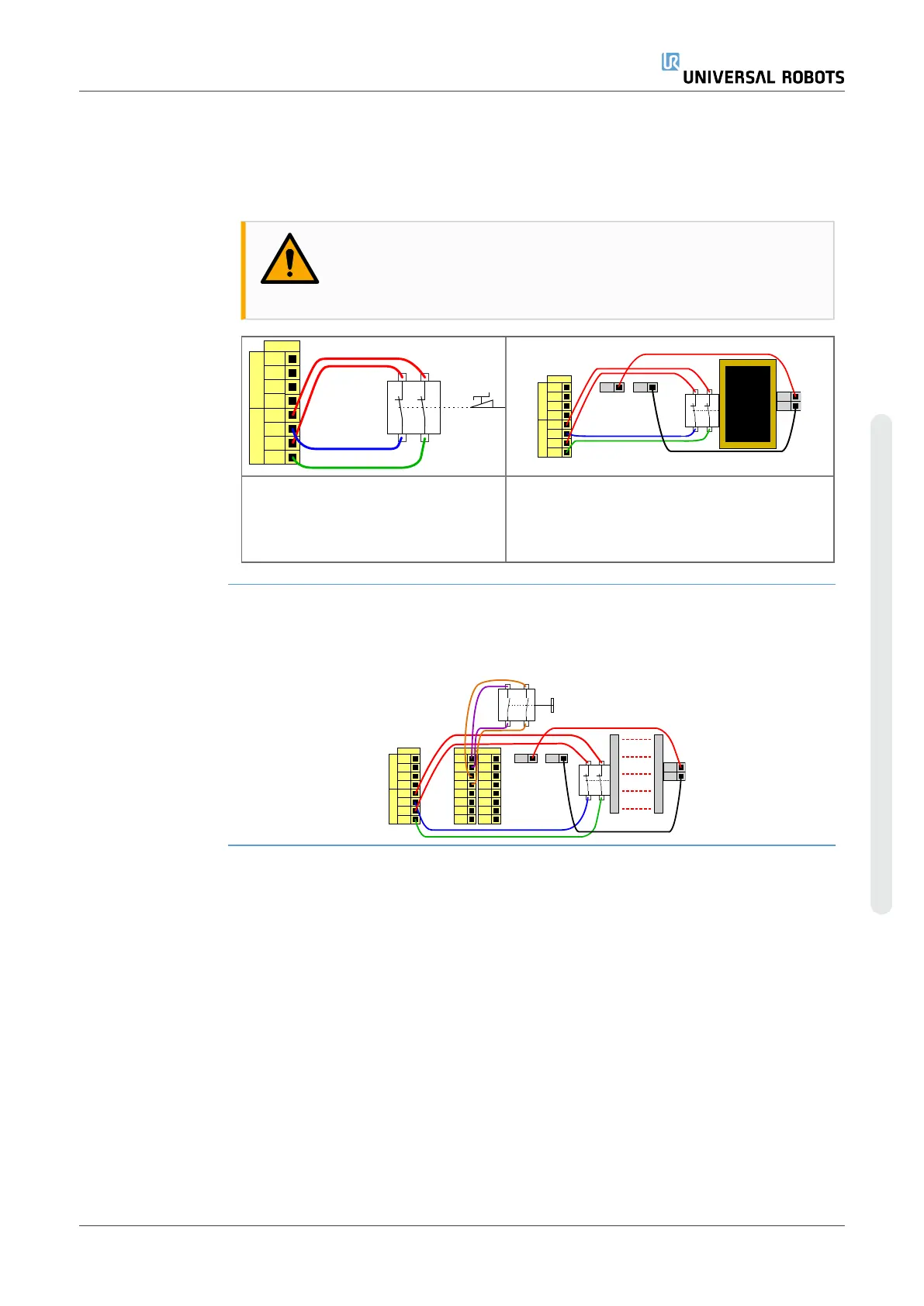
Using Tool Digital Outputs
This example illustrates turning on a load using the internal 12V or 24V power supply. The output
voltage at the I/O tab must be define. There is voltage between the POWER connection and the
shield/ground, even when the load is turned off.
User Manual 53 UR16e
2.Part I Hardware Installation Manual
Copyright © 2009–2024 by UniversalRobotsA/S. All rights reserved.