Configuring a Plane
Feature PCS
1. Create a plane feature by Adding a plane or Teaching a plane. See
.
2. Fix the part relative to the robot base.
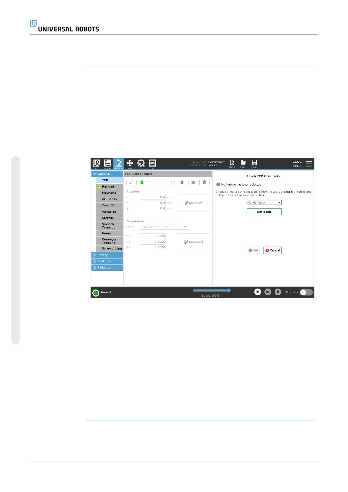
3. Verify the correct TCP is us to create the plane feature. For high
accuracy, temporarily set up a sharp Remote TCP to complete this
teaching process.
4. Jog the robot for the Remote TCP to touch the origin, positive X-axis
and the positive Y-axis direction of the PCS on the part.
5. Finish the teaching process and confirm the PCS position and
orientation.
Configuring a
Toolpath Node
1. Access the Program Tab and tap URCaps.
2. Select a TCP and set the motion parameters: tool speed, tool
acceleration and blend radius. Select Spin tool freely around its Z-
axis. Do not select if the tool must follow the orientation around Z-
axis defined in the toolpath file.
3. Tap +Toolpath to insert a Toolpath node.
4. In the drop-down menu, select a toolpath file and the corresponding
PCS (Plane Feature).
5. Adjust the motion parameters if different values are to be applied to
the Toolpath node.
6. Tap Move to First Point to verify the tool can move to the first point
of the toolpath.
7. Run the program in the simulation mode, at a low speed, to confirm
the configurations are correct.
NOTICE
You can ensure the robot motion is identical, each time the
toolpath is executed, by adding a MoveJ with a Use Joint
Angles set to move to a fixed joint configuration before
executing the toolpath. See 7.7.1. Moveon page187
UR16e 280 User Manual
Copyright © 2009–2024 by UniversalRobotsA/S. All rights reserved.