List of Figures 19
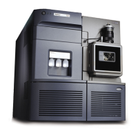
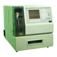
1-1 Waters 717plus Autosampler......................................................... 27
1-2 Waters 717plus Autosampler Subsystems .................................... 32
2-1 Waters 717plus Autosampler Site Requirements .......................... 34
2-2 Fluid Line Connections .................................................................. 37
2-3 Drain Line Connections ................................................................. 38
2-4 Autosampler Rear Panel................................................................ 39
2-5 Terminal Strip................................................................................. 42
2-6 IEEE-488 Connections .................................................................. 46
2-7 Removing the Autosampler Cover................................................. 48
2-8 Installing Heater/Cooler ................................................................. 50
2-9 Connecting the Heater/Cooler Power Cord and
Temperature Probe........................................................................51
2-10 Installing the Temperature Probe................................................... 52
2-11 Disconnecting the Sample Loop.................................................... 53
3-1 Power Switch Location................................................................... 55
3-2 Main Menu..................................................................................... 56
3-3 Front Panel .................................................................................... 57
3-4 717plus Autosampler Menu Flowchart .......................................... 58
3-5 Path to Auto Zero Pressure Page .................................................. 61
3-6 Path to Seal Pak Calibration Page................................................. 63
3-7 Priming the Needle Wash Pump.................................................... 64
3-8 Autosampler Configuration Flowchart............................................ 66
3-9 Setting the Integrator Report Delay ............................................... 69
3-10 Setting Terminal Signal Parameters............................................... 70
3-11 Setting IEEE-488 Address............................................................. 72
3-12 Configuration Page 3..................................................................... 73
3-13 Purge Menu................................................................................... 74
List of Figures