Maintenance
3303−5/A1
Winterthur Gas & Diesel Ltd.
3/ 4
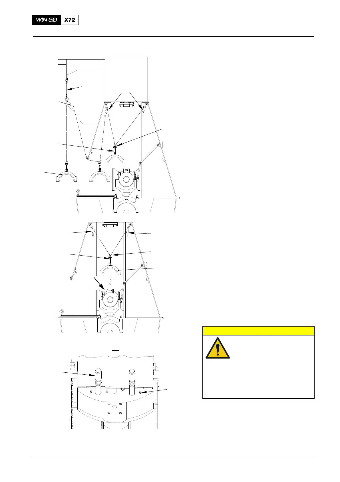
10) Attach the chain (94019B, Fig. 4) to the
gallery.
11) Attach the manual ratchet (94016-017)
to the chain (94019B).
12) Operate the two manual ratchets
(94016−025) to move the bearing cover
to the fuel side.
13) Lower the bearing cover a small
distance.
14) Attach the manual ratchet (94016-017)
to the shackle (94018B).
15) Operate the manual ratchets
(94016-017 and 94016−025) to move
the bearing cover (1) to the fuel side.
16) Lower the bearing cover (1) on to an
applicable surface.
17) If necessary, remove the chain
(94019C) from the bearing cover (1).
3. Installation
1) Make sure that the bearing cover (1)
has no damage.
2) If necessary, attach the chain (94019C)
to the bearing cover (1).
3) Operate the manual ratchets
(94016-017 and 94016−025) to move
the bearing cover (1) to a position near
the crosshead.
4) Carefully remove the manual ratchet
(94016-017) from the shackle (94018B.
5) Operate the manual ratchets
(94016−025) to move the bearing cover
(1, Fig. 5) to a position directly above
the elastic bolts.
CAUTION
Damage Hazard: Before
you operate the manual
ratchets, make sure that
the bearing cover is level
and vertically aligned with
the center of the
crosshead pin. This will
prevent damage to the
elastic bolts.
6) Carefully lower the bearing cover (1) on
to the crosshead pin. Make sure that
you do not damage the elastic bolts (2).
7) Make sure that the holes in the bearing
cover (1) engage with the four dowel
pins (2).
2015
Top End Bearing Cover − Removal, Inspection and Installation
94019B
94016−17
1
94016−025
94019C
Fig. 4
94018B
WCH02662
94016−025
94016−025
1
94018B
94019C
Fig. 5
WCH02662
I
I
2
3
WCH02664
 Loading...


