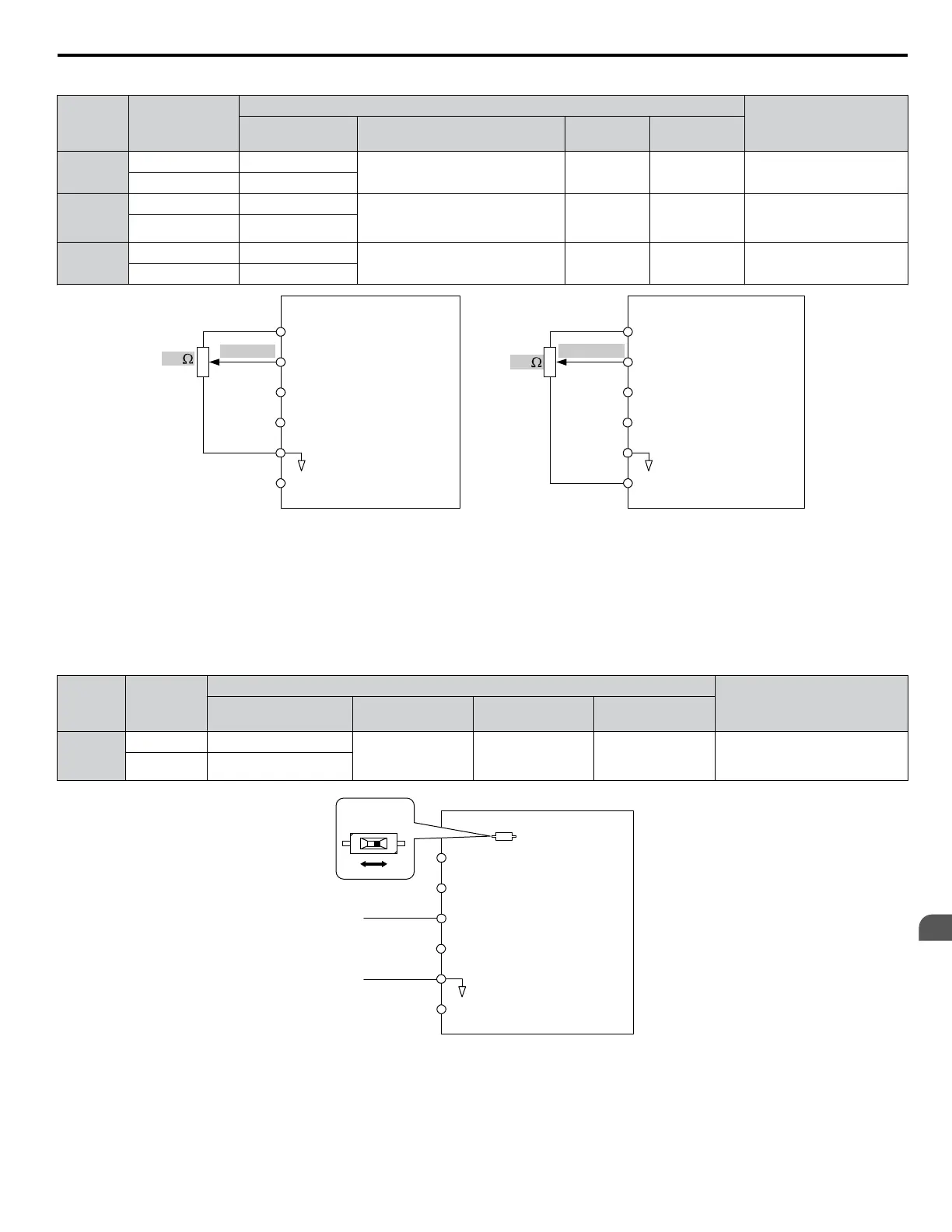
Table 4.6 Analog Input Settings for Frequency Reference Using Voltage Signals
Terminal Signal Level
Parameter Settings
Notes
Signal Level
Selection
Function Selection Gain Bias
A1
0 to 10 Vdc H3-01 = 0
H3-02 = 0
(Frequency Reference Bias)
H3-03 H3-04 –
-10 to +10 Vdc H3-01 = 1
A2
0 to 10 Vdc H3-09 = 0
H3-10 = 0
(Frequency Reference Bias)
H3-11 H3-12
Set DIP switch S1 on the
terminal board to “V” for
voltage input.
-10 to +10 Vdc H3-09 = 1
A3
0 to 10 Vdc H3-05 = 0
H3-06 = 0
(Frequency Reference Bias)
H3-07 H3-08
Set DIP switch S4 on the
terminal board to “AI”.
-10 to +10 Vdc H3-05 = 1
Drive
A1 Analog Input 1
0 to 10 V
AC Analog input common
2 k
+V
-V
10.5 V, 20 mA power supply
-10.5 V, 20 mA power supply
A2 Analog Input 2
A3 Analog Input 3
Drive
A1 Analog Input 1
AC Analog input common
+V
-V
10.5 V, 20 mA power supply
-10.5 V, 20 mA power supply
A2 Analog Input 2
A3 Analog Input 3
4 k
-10 to 10 V
OR
Figure 4.8 Setting the Frequency Reference as a Voltage Signal at Terminal A1
Use the wiring example shown in the figure above for any other analog input terminals. When using input A2 make sure DIP
switch S1 is set for voltage input.
Current Input
Input terminal A2 can accept a current input signal. Refer to Table 4.7 to set terminal A2 for current input.
Table 4.7
Analog Input Settings for Frequency Reference Using a Current Signal
Terminal
Signal
Level
Parameter Settings
Notes
Signal Level
Selection
Function
Selection
Gain Bias
A2
4 to 20 mA H3-09 = 2
H3-10 = 0
(Frequency Bias)
H3-11 H3-12
Make sure to set DIP switch S1 on
the terminal board to “I” for
current input.
0 to 20 mA H3-09 = 3
Drive
A1 Analog Input 1
0 or 4 to 20 mA
AC Analog input common
+V
-V
10.5 V, 20 mA power supply
-10.5 V, 20 mA power supply
A2 Analog Input 2
A3 Analog Input 3
DIP switch S1
V I
Figure 4.9 Setting the Frequency Reference as a Current Signal to Terminal A2
Switching between Main/Auxiliary Frequency References
The
frequency reference input can be switched between the analog terminals A1, A2, and A3 using multi-speed inputs. Refer
to Multi-Step Speed Selection on page 146 for details on using this function.
4.6 Basic Drive Setup Adjustments
YASKAWA ELECTRIC TOEP C710616 41G YASKAWA AC Drive - A1000 Quick Start Guide
137
4
Start-Up Programming
& Operation

 Loading...


