Setting 0: Ramp to Stop
When the Run command is removed, the drive will decelerate the motor to stop. The deceleration rate is determined by the
active deceleration time. The default deceleration time is set to parameter C1-02.
When the output frequency falls below the level set in parameter b2-01, the drive will start DC injection, Zero Speed Control,
or Short Circuit Braking, depending on the selected control mode. Refer to b2-01: DC Injection Braking Start Frequency
on page 141 for details.
V/f, V/f w/PG and OLV (A1-02 = 0, 1, 2)
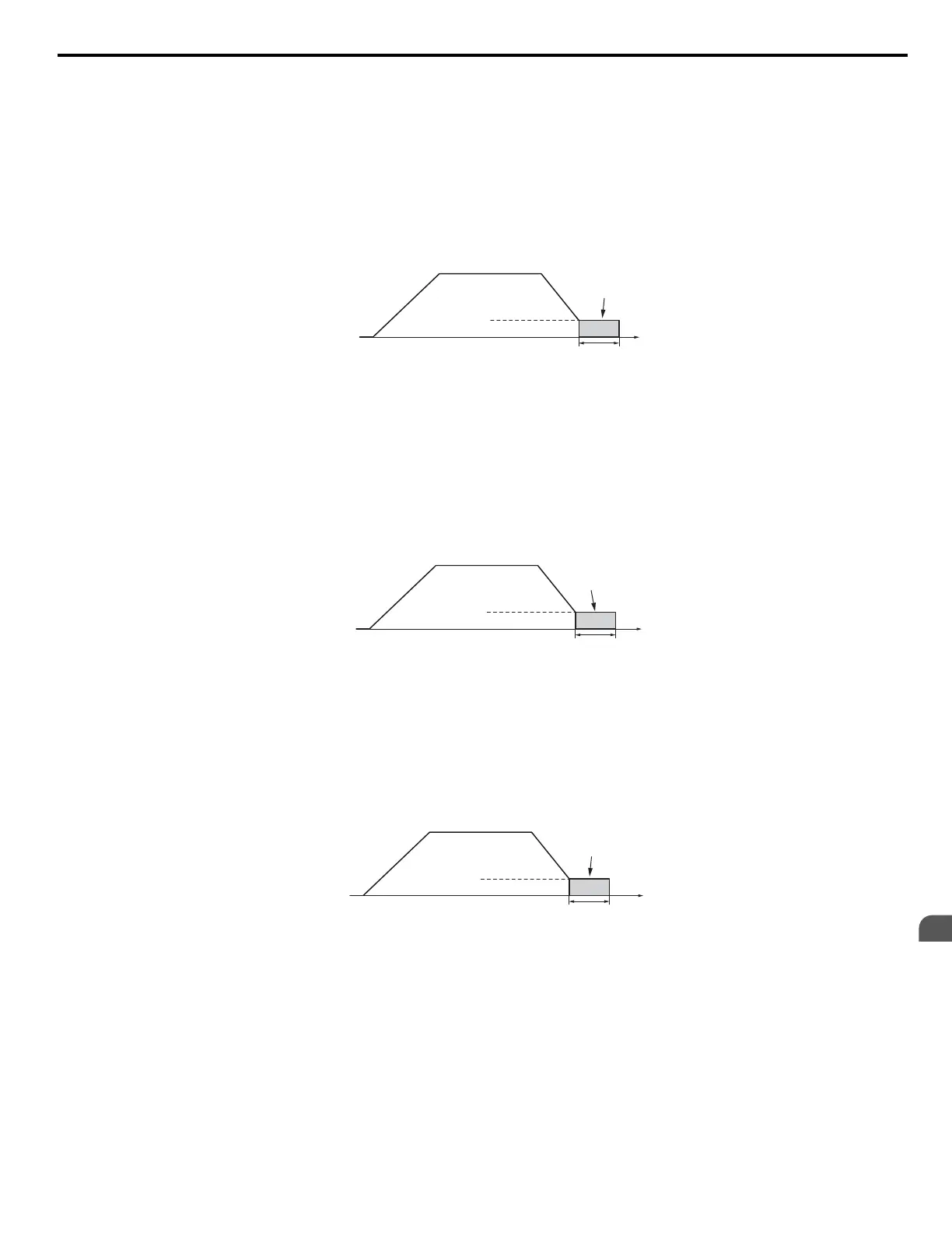
For these control modes, parameter b2-01 sets the starting frequency for DC Injection Braking at Stop. When the output
frequency falls below the setting of b2-01, DC Injection Braking is enabled for the time set in parameter b2-04.
Output
Frequency
Time
b2-04
DC Injection
Braking
E1-09 Min. Output Freq.
b2-01 DC Inj. Braking Start Freq.
Figure 4.10 DC Injection Braking at Stop for V/f, V/f w/PG, and OLV
Note: If b2-01 is set to a smaller value than E1-09 (Minimum Frequency), then DC Injection Braking will begin when the frequency falls to the
E1-09 value.
OLV/PM and AOLV/PM (A1-02 = 5, 6)
For these control modes, parameter b2-01 sets the starting frequency for Short-Circuit Braking at Stop. When the output
frequency falls below the setting of b2-01, Short-Circuit Braking is enabled for the time set in parameter b2-13.
If
DC Injection Braking Time is enabled at stop, then DC Injection Braking is performed for the time set in b2-04 after Short-
Circuit Braking is complete.
Output
Frequency
Time
b2-13
Short Circuit
Braking
E1-09 Min. Frequency
b2-01 Zero Speed Level
Figure 4.11 Short-Circuit Braking at Stop in OLV/PM and AOLV/PM
Note: If b2-01 is set to a smaller value than E1-09 (Minimum Frequency), then DC Injection Braking will begin when the frequency falls to the
E1-09 value.
The drive will not perform short-circuit braking when b2-01 = E1-09 = 0 Hz.
CLV and CLV/PM (A1-02 = 3, 7)
For
these control modes, parameter b2-01 sets the starting frequency for Zero Speed Control (not position lock) at Stop. When
the output frequency falls below the setting of b2-01, Zero Speed Control is enabled for the time set in parameter b2-04.
Time
Zero Speed
Control
b2-04
Output
Frequency
E1-09 Min. Output Freq.
b2-01 DC Inj. Braking Start Freq.
Figure 4.12 Zero Speed Control at Stop in CLV and CLV/PM
Note: If b2-01 is set to lower than E1-09 (Minimum Frequency), then Zero Speed Control begins at the frequency set to E1-09.
Setting 1: Coast to Stop
When
the Run command is removed, the drive will shut off its output and the motor will coast (uncontrolled deceleration) to
stop. The stopping time is determined by the inertia and the friction in the driven system.
4.6 Basic Drive Setup Adjustments
YASKAWA ELECTRIC TOEP C710616 41G YASKAWA AC Drive - A1000 Quick Start Guide
139
4
Start-Up Programming
& Operation

 Loading...


