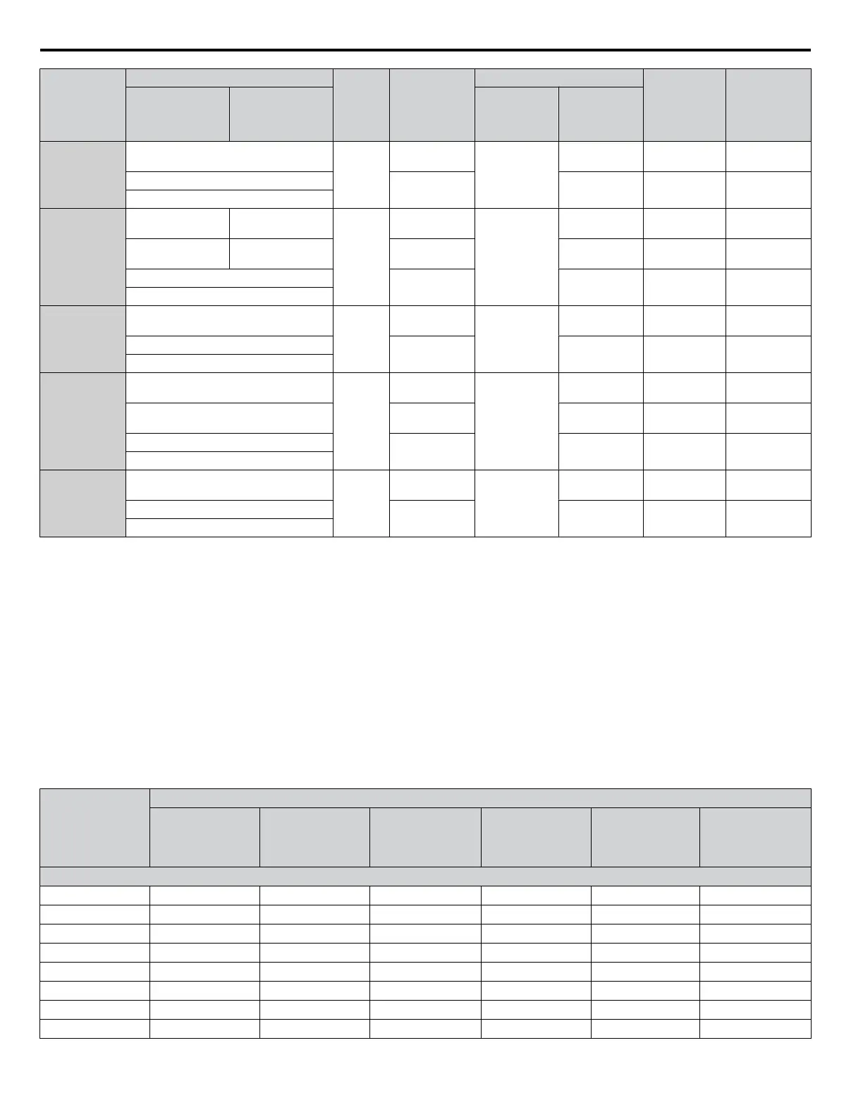
Drive Model
Wire Gauge (AWG, kcmil)
Screw
Size
Crimp
Terminal
Model
Number
Tool
Insulation
Cap Model
No.
Code
<1>
R/L1, S/L2, T/L3 U/T1, V/T2, W/T3 Machine No. Die Jaw
4A0414
4/0 × 2P
M12
100-L12
YF-1
YET-300-1
TD-324,
TD-312
TP-100 100-051-560
250 × 2P
150-L12
TD-325,
TD-313
TP-150 100-051-562
300 × 2P
4A0515
3/0 × 4P 3/0 × 4P
M12
80-L12
YF-1
YET-300-1
TD-323,
TD-312
TP-080 100-051-558
4/0 × 4P 4/0 × 4P 100-L12
TD-324,
TD-312
TP-100 100-051-560
250 × 4P
150-L12
TD-325,
TD-313
TP-150 100-051-562
300 × 2P
4A0675
4/0 × 4P
M12
100-L12
YF-1
YET-300-1
TD-324,
TD-312
TP-100 100-051-560
250 × 4P
150-L12
TD-325,
TD-313
TP-150 100-051-562
300 × 4P
4A0930
3/0 × 8P
M12
80-L12
YF-1
YET-300-1
TD-323,
TD-312
TP-080 100-051-558
4/0 × 8P 100-L12
TD-324,
TD-312
TP-100 100-051-560
250 × 8P
150-L12
TD-325,
TD-313
TP-150 100-051-562
300 × 8P
4A1200
4/0 × 8P
M12
100-L12
YF-1
YET-300-1
TD-324,
TD-312
TP-100 100-051-560
250 × 8P
150-L12
TD-325,
TD-313
TP-150 100-051-562
300 × 8P
<1> Codes refer to a set of three crimp terminals and three insulation caps. Prepare input and output wiring using two sets for each connection.
Example
1: Models with 300 kcmil for both input and output require one set for input terminals and one set for output terminals, so the user should
order two sets of [100-051-272].
Example 2: Models with 4/0 AWG × 2P for both input and output require two sets for input terminals and two sets for output terminals, so the user
should order four sets of [100-051-560].
Note: Use crimp insulated terminals or insulated shrink tubing for wiring connections. Wires should have a continuous maximum allowable
temperature of 75 °C 600 Vac UL-approved vinyl-sheathed insulation.
Factory Recommended Branch Circuit Protection for UL Compliance
NOTICE: If a fuse is blown or a Ground Fault Circuit Interrupter (GFCI) is tripped, check the wiring and the selection of the peripheral devices
to identify the cause. Contact Yaskawa before restarting the drive or the peripheral devices if the cause cannot be identified.
Yaskawa recommends installing one of the following types of branch circuit protection to maintain compliance with UL508C.
Semiconductor protective type fuses are preferred. Alternate branch circuit protection devices are also listed in the tables
below.
Table C.7 Factory Recommended Drive Branch Circuit Protection (Normal Duty)
Drive Model
Normal Duty
Nominal
Output Power
HP
AC Drive Input
Amps
MCCB Rating
Amps
<1>
Time Delay Fuse
Rating Amps
<2>
Non-time Delay
Fuse Rating
Amps
<3>
Bussmann Semi-
conductor Fuse
Rating (Fuse
Ampere)
<4>
200 V Class
2A0004 0.75 3.9 15 6.25 10 FWH-70B (70)
2A0006 1 - 1.5 7.3 15 12 20 FWH-70B (70)
2A0008 2 8.8 15 15 25 FWH-70B (70)
2A0010 3 10.8 20 17.5 30 FWH-70B (70)
2A0012 3 13.9 25 20 40 FWH-70B (70)
2A0018 5 18.5 35 30 50 FWH-90B (90)
2A0021 7.5 24 45 40 70 FWH-90B (90)
2A0030 10 37 60 60 110 FWH-100B (100)
C.2 UL and CSA Standards
344
YASKAWA ELECTRIC TOEP C710616 41G YASKAWA AC Drive - A1000 Quick Start Guide

 Loading...


