5.3 MEMOBUS/Modbus Communications
306 YASKAWA SIEPC71061723A YASKAWA AC Drive CR700 Technical Manual
■ Function Code
There are five function codes that set commands.
Table 5.4 shows the different codes.
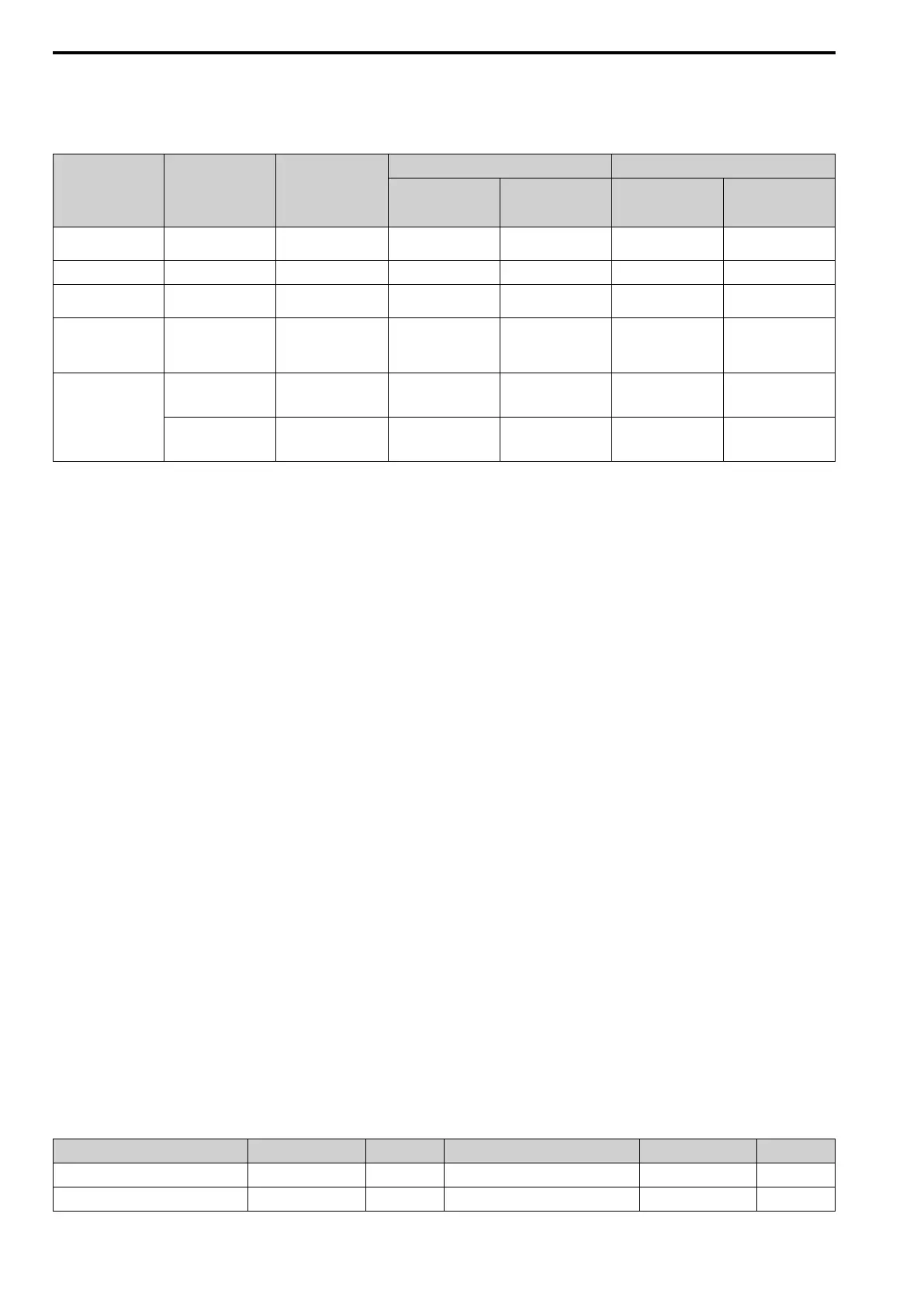
Table 5.4 Function Codes
Function Code
(Hex.)
Subfunction Code
(Hex.)
Function
Command Message Response Message
Minimum Data
Length
(byte)
Maximum Data
Length
(byte)
Minimum Data
Length
(byte)
Maximum Data
Length
(byte)
03 -
Read Multiple Holding
Registers
8 8 7 37
08 - Loopback Test 8 8 8 8
10 -
Writing to Multiple
Holding Registers
11 41 8 8
5A -
Writing to Multiple
Holding Registers /
Reading the Register
Indicated
11 41 17 17
67
010D
Reading the Contents
of Non-Consecutive
Holding Registers
10 248 10 248
010E
Writing to Non-
Consecutive Holding
Registers
14 250 8 8
■ Communications Data
Communications data is a series of data that uses the combination of the communications register number and the
data for these registers. The data length changes when the description of the command changes. For a loopback
test, it switches to test code.
The communications register for the drive has a 2-byte length. Data that is written to the register for the drive is
usually 2 bytes. Register data that is read from the drive is also 2 bytes.
■ Error Check
Error check uses the CRC-16 method to detect transmission errors. Use the procedure in this section to calculate
CRC-16.
Command Data
When the drive receives data, it will make sure that there are no errors in the data. The drive uses the procedure
below to calculate CRC-16, then the drive compares that data with the CRC-16 value in the message. If the CRC-
16 values do not agree, the drive will not execute a command message.
When you calculate CRC-16 in MEMOBUS/Modbus communications, make sure that you set the start value as
FFFF (Hex.). All 16 bits must be 1.
Use this procedure to calculate CRC-16:
1. Make sure that the start value is FFFF (Hex.).
2. Calculate the FFFF (Hex.) start value and the XOR of the slave address (exclusive OR).
3. Move the step 2 results one column to the right. Do this shift until the carry bit is 1.
4. When the carry bit is 1, calculate XOR via the result from the above step 3 and A001 (Hex.).
5. Do steps 3 and 4 until the 8th shift to the right.
6. Use the result of step 5 to calculate the XOR and the data of the following messages (function code, register
address, data). Do steps 3 to 5 until the last data, then calculate.
7. The result of the last right shift or the value of the last XOR calculation is the result for CRC-16.
Table 5.5 lists examples of the CRC-16 calculation of slave address 02 (Hex.) and function code 03 (Hex.). The
calculated results of CRC-16 for this section is D140 (Hex.).
Note:
The calculation example only gives information about some error checks with CRC-16. The drive will do the same error checks for the
next data.
Table 5.5 CRC-16 Calculation Example
Description Calculation Overflow Description Calculation Overflow
Initial value (FFFF (Hex.)) 1111 1111 1111 1111 - Function code 03 (Hex.) 0000 0011 -
Address 02 (Hex.) 0000 0010 - XOR w result 1000 0001 0011 1101 -

 Loading...


