11.7 F: Options
654 YASKAWA SIEPC71061723A YASKAWA AC Drive CR700 Technical Manual
■ F1-10: Speed Deviation Detection Level
No.
(Hex.)
Name Description
Default
(Range)
F1-10
(0389)
Speed Deviation Detection
Level
Sets the detection level of dEv [Speed Deviation] as a percentage when the maximum output
frequency is 100%.
10%
(0 - 50%)
When the speed deviation between the frequency reference and the actual motor speed is more than the value set
in F1-10 for longer than the time set in F1-11 [Speed Deviation Detect DelayTime], the drive will detect dEv.
■ F1-11: Speed Deviation Detect DelayTime
No.
(Hex.)
Name Description
Default
(Range)
F1-11
(038A)
Speed Deviation Detect
DelayTime
Sets the length of time that the difference between the frequency reference and speed feedback
must be more than the level in F1-10 to cause dEv [Speed Deviation].
0.5 s
(0.0 - 10.0 s)
When the speed deviation between the frequency reference and the actual motor speed is more than the value set
in F1-10 [Speed Deviation Detection Level] for longer than the time set in F1-11, the drive will detect dEv.
■ F1-12: Encoder 1 Gear Teeth 1
No.
(Hex.)
Name Description
Default
(Range)
F1-12
(038B)
Encoder 1 Gear Teeth 1
Sets the number of gear teeth on the motor side. This parameter and F1-13 [Encoder 1 Gear Teeth
2] set the gear ratio between the motor and encoder.
0
(0 - 1000)
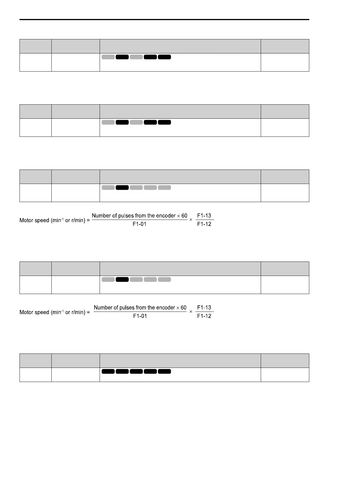
After you set the number of gear teeth, the drive uses this formula to calculate the motor speed:
Note:
When F1-12 = 0 or F1-13 = 0, the gear ratio is 1.
■ F1-13: Encoder 1 Gear Teeth 2
No.
(Hex.)
Name Description
Default
(Range)
F1-13
(038C)
Encoder 2 Gear Teeth 1
Sets the number of gear teeth on the load side. This parameter and F1-12 [Encoder 1 Gear Teeth
1] set the gear ratio between the motor and encoder.
0
(0 - 1000)
After you set the number of gear teeth, the drive uses this formula to calculate the motor speed:
Note:
When F1-12 = 0 or F1-13 = 0, the gear ratio is 1.
■ F1-14: Encoder Open-Circuit Detect Time
No.
(Hex.)
Name Description
Default
(Range)
F1-14
(038D)
Encoder Open-Circuit
Detect Time
Sets the detection time for PGo [Encoder (PG) Feedback Loss].
2.0 s
(0.0 - 10.0 s)
PGo is detected when the drive does not detect output pulses from the encoder for an amount of time longer than
or equal to the value set in F1-14.
Note:
Faults such as ov [Overvoltage] and oC [Overcurrent] may occur depending on the motor speed and load conditions.

 Loading...


