11.1 Addition of I/O Modules
11-2
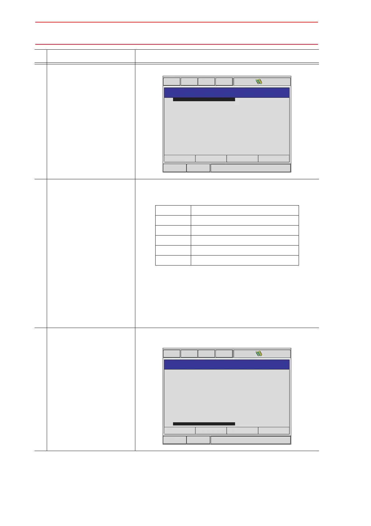
5 Select {IO MODULE}. The current status of the mounted I/O module is shown.
6 Confirm the status of mounted
I/O module.
Confirm that each station (ST#) window is the same as the I/O
module’s actual mounting status.
The following information is shown for each station.
*1 A hyphen, -, indicates that the corresponding I/O
section is not mounted.
*2 If the system cannot recognize the circuit board
type, a row of stars (*****) are
shown.
No problem will occur as long as the values dis-
played in DI, DO, AI, and AO are correct.
7 Press [ENTER]. Confirm the statuses of the mounted I/O modules for the other
stations.
Operation Explanation
Short CutMain Menu
Maintenance mode
IO MODULE
ST# DI DO AI AO BOARD
0040
0008
-
-
-
-
-
-
-
-
-
-
-
00
01
02
03
04
05
06
07
08
09
10
11
12
0040
0008
-
-
-
-
-
-
-
-
-
-
-
-
002
-
-
-
-
-
-
-
-
-
-
-
-
002
-
-
-
-
-
-
-
-
-
-
-
NI001-02
XEW02
NONE
NONE
NONE
NONE
NONE
NONE
NONE
NONE
NONE
NONE
NONE
ST# Station address of I/O module
DI Number of contact input points (
*1)
DO Number of contact output points (
*1)
AI Number of analog input points (
*1)
AO Number of analog output points (
*1)
BOARD Circuit board type (
*2)
Short CutMain Menu
Maintenance mode
IO MODULE
ST# DI DO AI AO BOARD
-
-
-
-
-
-
-
-
-
-
-
-
-
05
06
07
08
09
10
11
12
13
14
15
16
17
-
-
-
-
-
-
-
-
-
-
-
-
-
-
-
-
-
-
-
-
-
-
-
-
-
-
-
-
-
-
-
-
-
-
-
-
-
-
-
NONE
NONE
NONE
NONE
NONE
NONE
NONE
NONE
NONE
NONE
NONE
NONE
NONE

 Loading...


