13.2 Power Supply Contactor Sequence Circuit Board (JANCD-NTU01-)
13-8
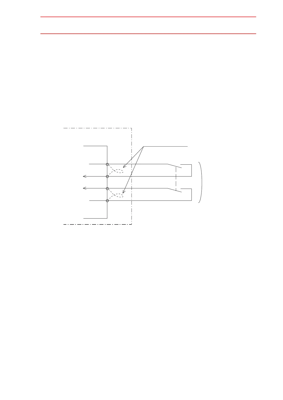
Connection for Servo-ON Enable Input (ON_EN1 and ON_EN2)
Connect the ON_EN signal lines to enable the function to turn ON or OFF the servo power
supply of an individual servo when a robotic system is divided into areas. Because these
signals are not used for units of standard specifications, a jumper cable is connected as
shown in the following figure.
For safety reasons, dual circuits are used for the Servo-ON Enable input signals. Connect the
signal so that both input signals are turned ON or OFF at the same time. If only one signal is
turned ON, an alarm occurs.
Refer to “8 Servo Power Supply Individual Control Function” of “Independent/Coordinated
Function Instructions Manual” for the usage of the Servo-ON Enable signals.
Fig. 4 Connection for Servo-ON Enable Input
NX100
CN06
-1
-2
-3
-4
+24V2
ONEN1
ONEN2
024V
Servo-ON enable input signal
Turn ON/OFF
at the same time
Power supply contactor unit
JZRCR-NTU
Remove the jumper cable

 Loading...


