8.3 Tool Data Setting
8-19
<Setting Example>
3 (Continued from the previous
page.)
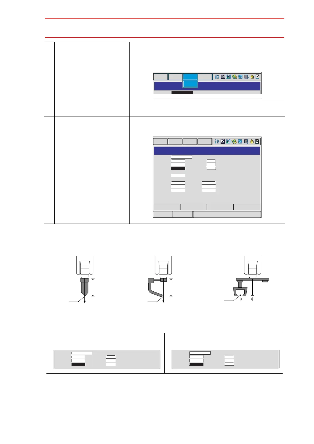
To switch the TOOL window and the coordinate window, press
{DISPLAY} {LIST} or {DISPLAY} {COORDINATE DATA}.
4 Select the desired coordinate
axis to modify.
The number input line is shown.
5 Input the tool data.
6 Press [ENTER]. The tool data is registered.
In Case of Tool A, B In Case of Tool C
Operation Explanation
TOOL
DATA EDIT UTILITY
TOOL NO. : 0 / 24
NAME
X
0.000
mm
Rx
0.00
deg.
DISPLAY
LIST
RB1 STD TOOL
_
_
Short CutMain Menu
TOOL
DATA EDIT DISPLAY UTILITY
TOOL NO. : 0 / 24
NAME
X
Y
Z
W
Xg
Yg
Zg
mm
mm
mm
kg
mm
mm
mm
Rx
Ry
Rz
Ix
Iy
Iz
0.00
0.00
0.00
0.000
0.000
0.000
deg.
deg.
deg.
kg.m2
kg.m2
kg.m2
RB1 STD TOOL
_
_
0.000
0.000
260.000
0.000
0.000
0.000
0.000
PAGE
Z
F
TCP
Tool A
260 mm
145 mm
Z
F
260 mm260 mm
TCP
TCP
Tool B Tool C
NAME
X
Y
Z
mm
mm
mm
Rx
Ry
Rz
0.00
0.00
0.00
deg.
deg.
deg.
RB1 STD TOOL
_
_
0.000
0.000
260.000
NAME
X
Y
Z
mm
mm
mm
Rx
Ry
Rz
0.00
0.00
0.00
deg.
deg.
deg.
RB1 STD TOOL
_
_
0.000
145.000
260.000

 Loading...


