3-3
IM 05P02C41-01EN
Part Names
3
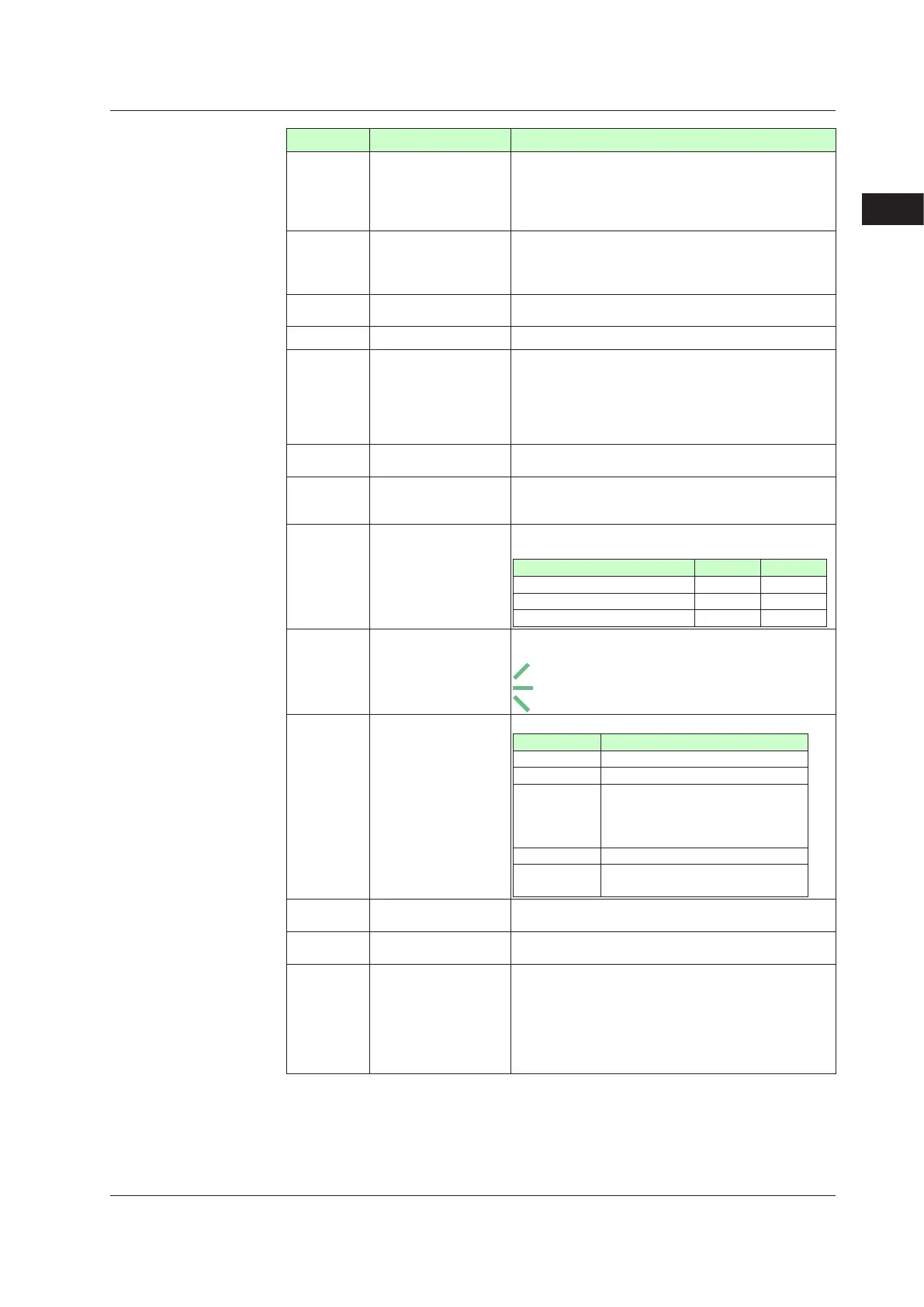
No.ingure Name Description
(1)
PVdisplay
(whiteorred)
Displays PV.
Displays an error code if an error occurs.
Displays the scrolling guide in the Menu Display and
Parameter Setting Display when the guide display ON/
OFF is set to ON.
(2)
Groupdisplay
(pattern number)
(green)
1to30or99(99whentheoption“/AP”isspecied)
represent pattern numbers in the Operation Display.
Displays a group number (1 to 8 or R) and terminal area (E1
to E4) in the Parameter Setting Display.
(3)
Symboldisplay
(orange)
Displays a parameter symbol.
(4) Datadisplay(orange) Displays a parameter setpoint and menu symbol.
(5)
Bar-graphdisplay
(event,alarm)
(orange)
Displays the event status and the segment position in the
Operation Display. (Default values: Time event status,
Alarm status)
Displays control output value (OUT) and measured input
value (PV).
The data to be displayed can be set by the parameter.
(6)
Eventindicator
(orange)
Lit when the PV events occur.
Event displays can be set by the parameter.
(7)
Keynavigation
indicator
(green)
Lit or blinks when the Up/Down or Left/Right arrow key
operation is possible.
(8)
Parameterdisplay
levelindicator
(green)
Displays the setting conditions of the parameter display
level function.
Parameterdisplaylevel EASY PRO
Easy setting mode Lit Unlit
Standard setting mode Unlit Unlit
Professional setting mode Unlit Lit
(9)
Program monitor
(green)
Displays the status of increment, constancy, and
decrement of the program setpoint.
: Lit when a program setpoint is increasing.
: Lit when a program setpoint is constant.
: Lit when a program setpoint is decreasing.
(10)
Statusindicator
(green and red)
Displays the operating conditions and control status.
Display Description
HLD Lit when in remote mode (HOLD).
CAS Lit when in cascade mode (CAS).
PRG
Lit when in program operation mode
(PRG).
Lit while the Starting time of program
operation (S.TM) is available.
RST Lit when in reset mode (RST).
MAN
Lit when in manual mode (MAN).
Blinks during auto-tuning.
(11) Securityindicator(red)
Lit if a password is set. The setup parameter settings are
locked.
(12)
Ladder operation
indicator (green)
Lit while the ladder program operation is executed.
(13
Loop2indicator
(LP2lamp)
(green)
Lit when the control mode is Cascade control.
In the Operation Display, the LP2 lamp is lit while the
Loop-2 data is displayed on Setpoint display.
In the Parameter Setting Display, the LP2 lamp indicates
the loop of displayed menu symbol or parameter symbol.
The LP2 lamp is lit while the Loop-2 menu symbol or
parameter symbol is displayed.
3.1NamesandFunctionsofDisplayParts

 Loading...


