17-6
IM 05P02C41-01EN
CAUTION
Do not use an unassigned terminal as the relay terminal.
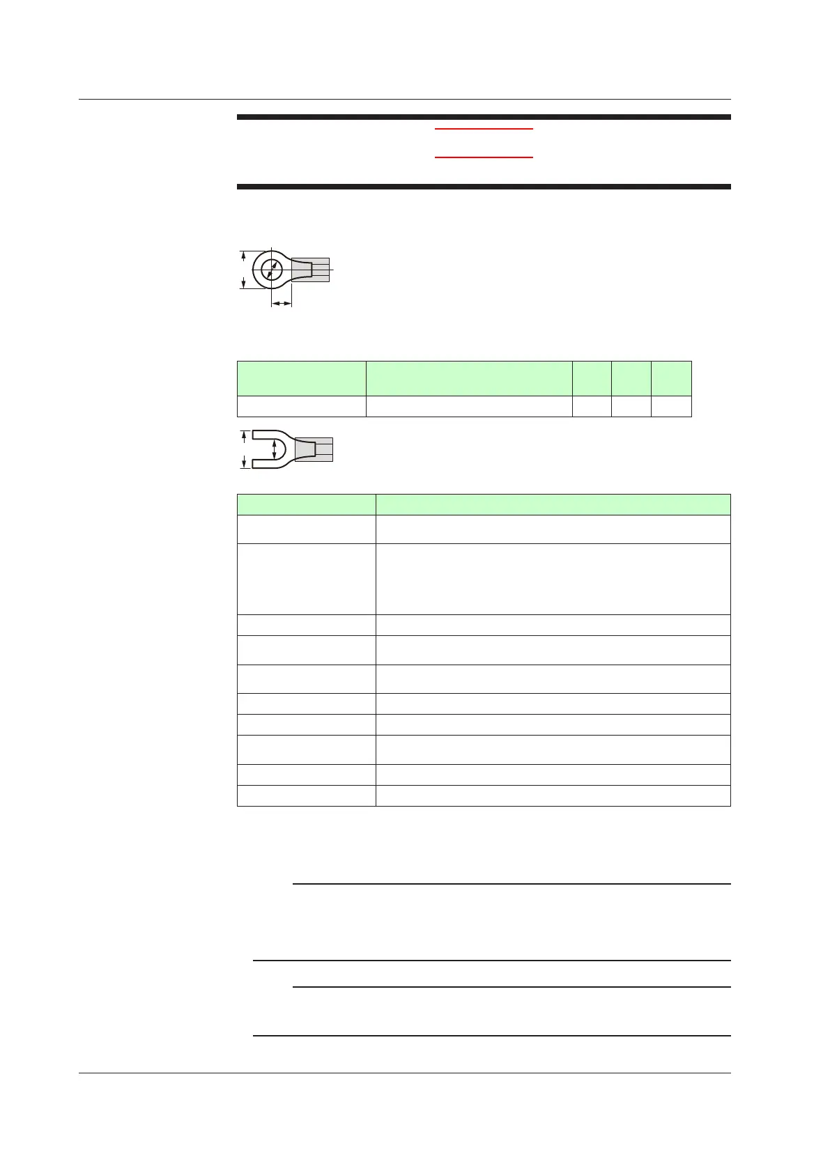
RecommendedCrimp-onTerminalLugs
(F)
Recommended tightening torque: 0.6 N·m
Applicablewiresize:Powersupplywiring1.25mm
2
or more
Applicable terminal lug Applicablewiresizemm
2
(AWG#) (ød) (A) (F)
M3 0.25 to 1.65 (22 to 16) 3.3 5.5 4.2
3.3
CableSpecifications
Purpose Name and Manufacturer
Power supply, relay contact
output
600 V Grade heat-resistant PVC insulated wires, JIS C 3317(HIV), 0.9
to 2.0 mm
2
Thermocouple
Shielded compensating lead wire JISC1610
For thermocouple input (PV input and remote input with direct input),
shielded compensating lead wire of cross-sectional area less than or
equal to 0.75 mm
2
is recommended. If the crosssectional area is wide,
thereferencejunctioncompensationerrormaybelarge.
RTD Shielded wire (three/four conductors) UL2482 (Hitachi Cable)
Other signals (other than
contact input/output)
Shielded wires
Other signals (contact
input/output)
Non shielded wires
RS485 communication Shielded wires
Ethernet communication 100BASE-TX(CAT-5)/10BASE-T
PROFIBUS-DP
communication
Dedicated cable for PROFIBUS-DP (Shielded two-wires)
DeviceNet communication DedicatedcableforDeviceNet(Shieldedve-wires)
CC-Link communication Dedicated cable for CC-Link (Shielded three-wires)
PROFIBUS-DP/CC-LinkConnector(wiringside)(Partnumber:A1987JT)
DeviceNetConnector(wiringside)(Partnumber:L4502BW)
Recommended tightening torque: 0.5 to 0.6 N·m
Note
Communication wires of cross-sectional area less than or equal to 0.34 mm
2
may not be
secured firmly to the terminals.
Check that the wire is firmly connected to the terminal by folding the conductor of the wire
connected to the climp-on lug.
Recommended length of the stripped wire: 7 mm
Note
If the UP is located at the end of a segment for the PROFIBUS communication wiring,
terminatingresistorsareseparatelyneeded.Thesearetobepreparedbyusers.(390Ω:2pcs.
220Ω:1pc.,oranactiveterminator.)
17.4Wiring

 Loading...


