17-30
IM 05P02C41-01EN
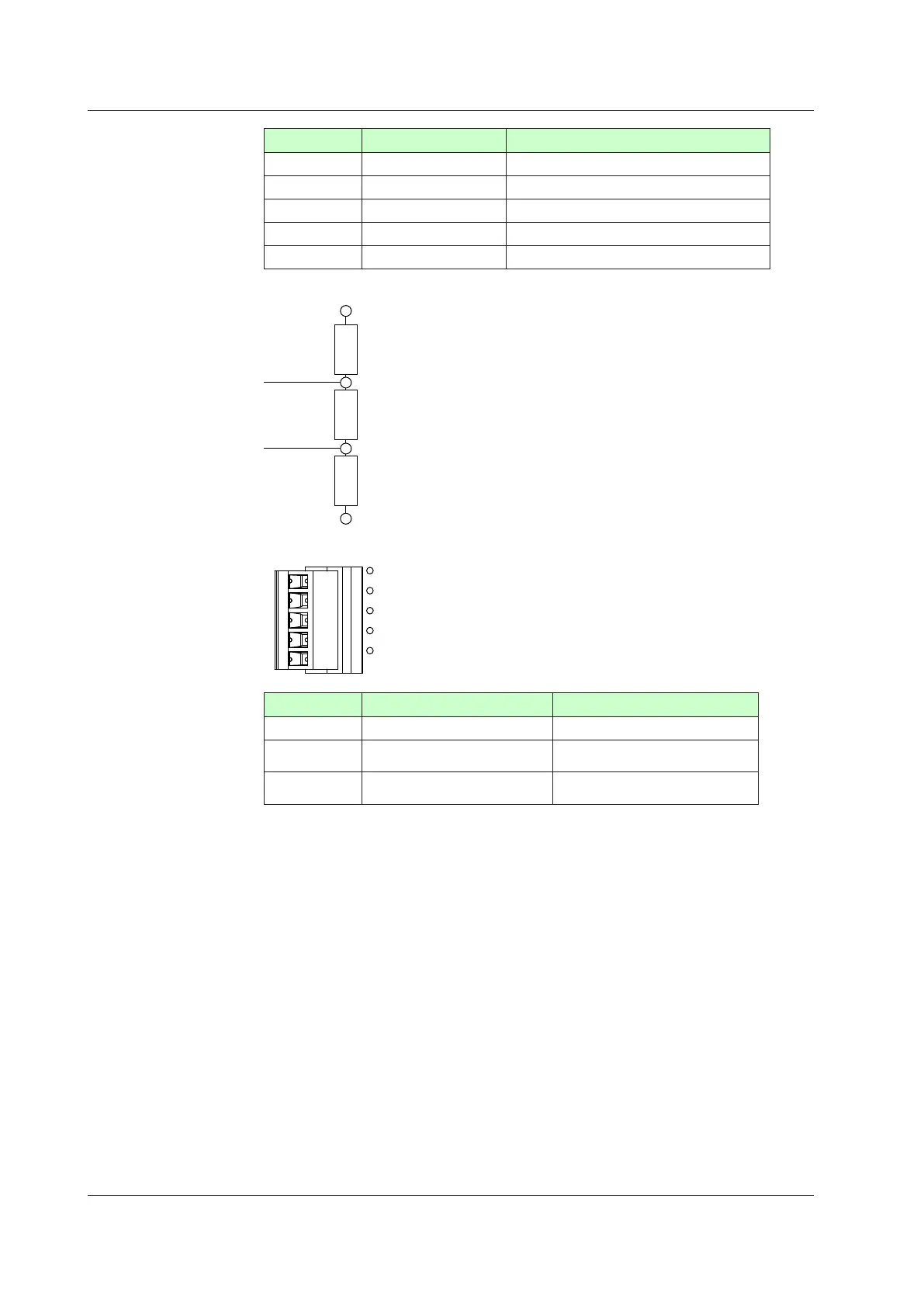
NumberofPin Singnalname Description
1 VP +5V bus power
2 RxD/TxD-P Data signal (positive data receive/transmit)
3 RxD/TxD-N Data signal (negative data recive/transmit)
4 DGND Signal ground
5 SHIELD Shield ground
TerminatingResisterofBus
RxD/TxD-P
Data line
Data line
390Ω
220Ω
390Ω
RxD/TxD-N
PROFIBUS-DPcommunicationconnectorandLED
CHK
RDY
ERR
LED Lit Unlit
CHK (red) Userproleerror Normal
RDY (green)
Normal.
Communicating successfully.
No electricity, or Communication
failure
ERR (red)
Not connected, or communication
failure(ashing)
Normal
Modbusmasterwiring
Modbus master wiring is same as RS-485 communication wiring for Ethernet-serial
gateway function.
17.4Wiring

 Loading...


