17-32
IM 05P02C41-01EN
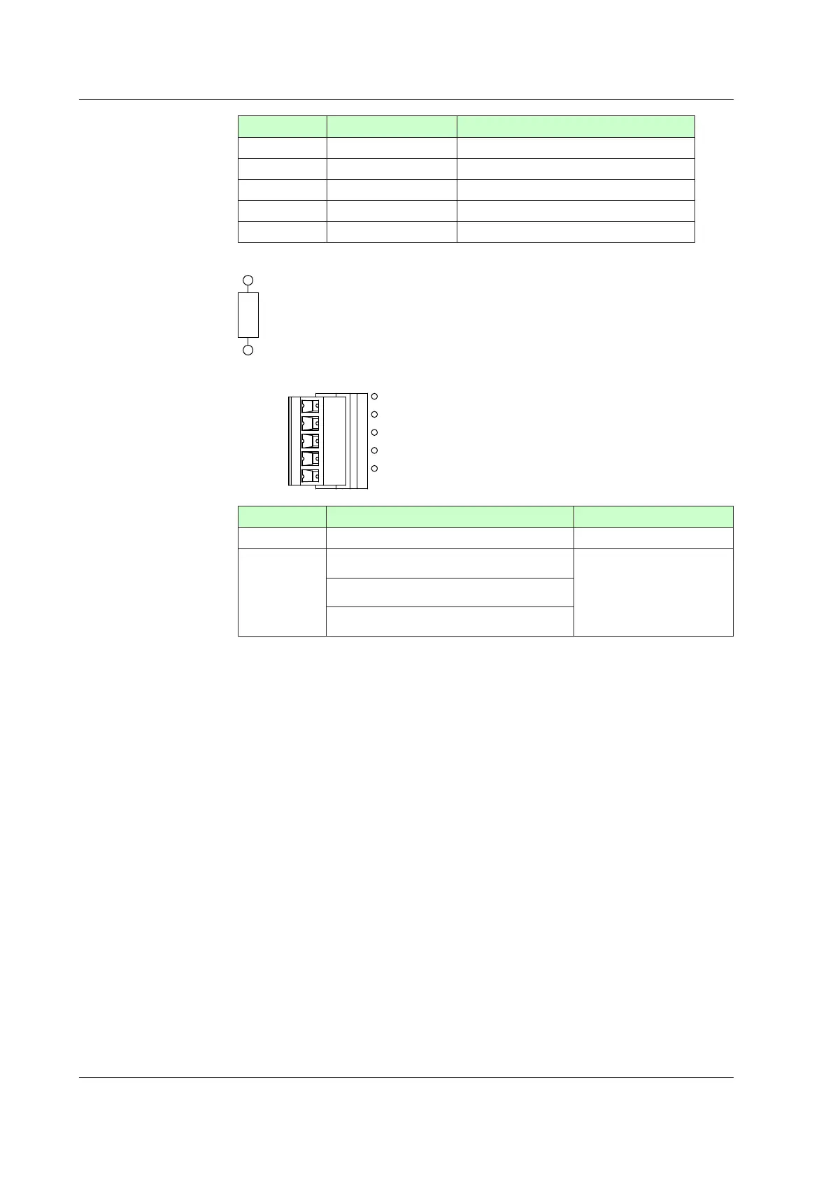
NumberofPin Singnalname Description
1 V+ Power supply 24V for DeviceNet
2 CAN_H RX/TX+signal
3 DRAIN Shield/drain
4 CAN_L RX/TX-signal
5 V- Power supply COM for DeviceNet
TerminatingResisterofBus(bothendsofthetrunkline)
121Ω
DeviceNetcommunicationconnectorandLED
CHK
MNS
1
2
3
4
5
(Red)
(White)
(Blue)
(Black)
LED Lit/ashing Unlit
CHK (red) Userproleerror Normal
MNS (green/red)
Normal. Communicating successfully (green, lit).
Notconnected(green,ashing).
No electricity,
Critical link failure (red, lit).
Connectiontimeout(red,ashing)
At power-on/Communication faulted (green/red,
ashing)
Modbusmasterwiring
Modbus master wiring is same as RS-485 communication wiring for Ethernet-serial
gateway function.
17.4Wiring

 Loading...


