18-13
IM 05P02C41-01EN
Parameters
18
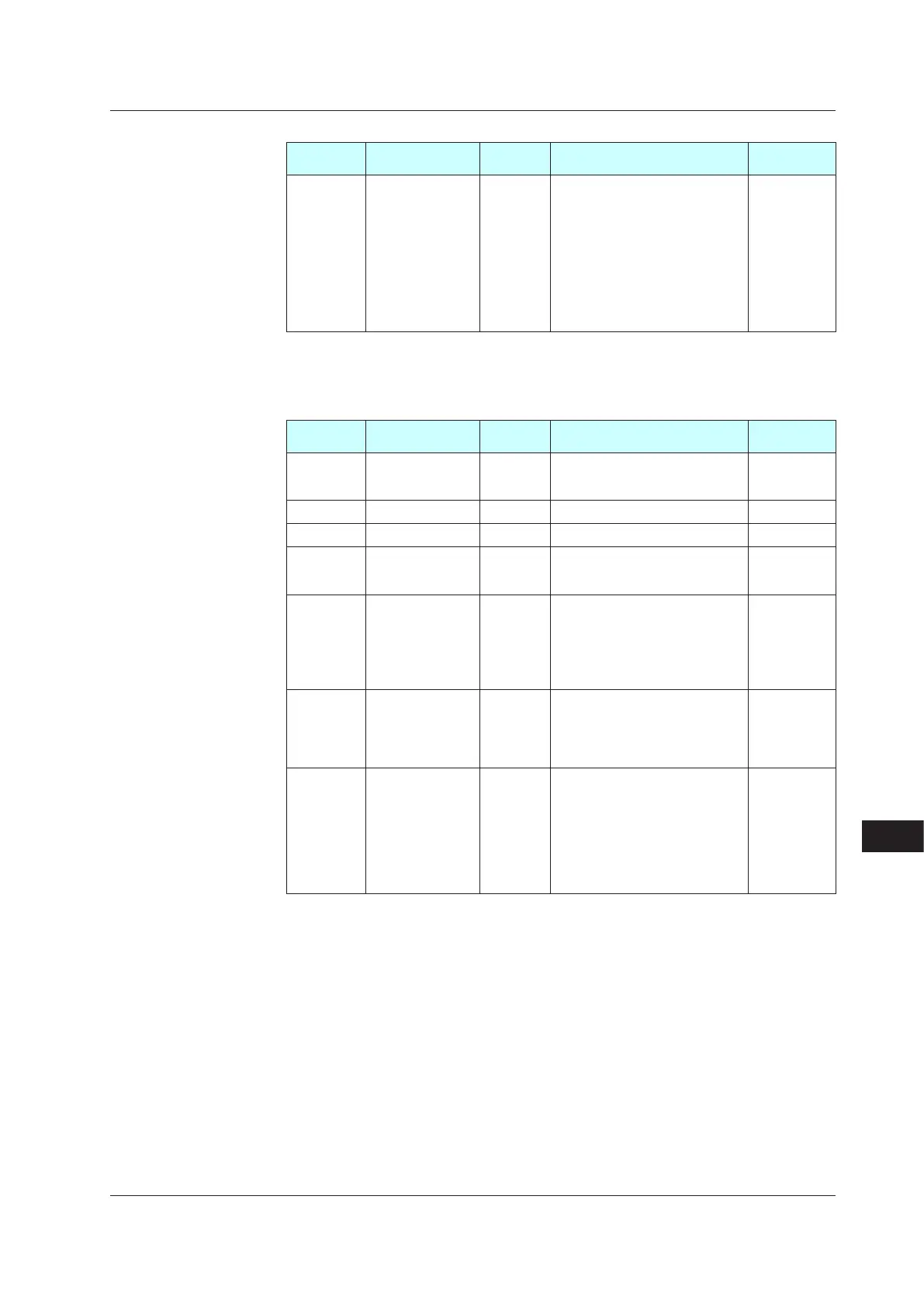
AlarmSetpointSettingMenu(Menu:AL)
Parameter
symbol
Name
Display
level
Settingrange Initialvalue
A1toA8
Alarm-1 to -8
setpoint
EASY
These alarms work irrespective of
the operation mode.
Set a display value of setpoint of
PV alarm, SP alarm, deviation
alarm, output alarm, or velocity
alarm.
-19999 to 30000 (Set a value
within the input range.)
Decimal point position depends on
the input type.
0
In Cascade control, the following parameters are also displayed for secondary loop. (the LP2 lamp
is lit)
• Parameter: A1 to A8
SP-relatedSettingMenu(Menu:SPS)
Parameter
symbol
Name
Display
level
Settingrange Initialvalue
RMS
Remote input
method
STD
RSP: Via remote (aux. analog)
input
COM: Via communication
RSP
RFL Remoteinputlter STD OFF, 1 to 120 s OFF
RT Remote input ratio STD 0.001 to 9.999 1.000
RBS Remote input bias STD
-100.0 to 100.0% of PV input range
span (EUS)
0.0 % of PV
input range
span
SPT
SP tracking
selection
STD
OFF, ON
Tracking is performed when the
mode changes from Program
or Remote to Local. (The local
setpoint keeps track of the remote
setpoint.)
OFF
S.TM
Starting time of
program operation
STD
0.00 to 999.59 (“hour.minute” or
“minute.second” (common use of
instrument)
* Use the parameter TMU to set
the time unit.
0.00
PNC
Program pattern
number clearance
STD
OFF: Not cleared.
ON: Cleared. (Set the program
No. before restart program
operation)
* The controller resets (clears) the
program pattern number on the
operating display to “0” at the
end of program operation.
OFF
18.2ListofParameters

 Loading...


