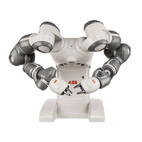
The illustration shows the hole configuration used when securing the robot.
324
286
2
0
-
40
80
6
+
+
0.025
0.015
(A)
8x M5
57
24
8
H
1
.
6
0.2
2
6
+
+
0.025
0.015
(B)
1.6
DETAIL H
xx1400002121
Master hole (round)A
Alignment hole (slot)B
Specification, attachment screws and pins
The table specifies the type of securing screws to be used to secure the robot
directly to the foundation. It also specifies the type of pins to be used.
M5x25Screws
8 pcsQuantity
8.8Quality
8 pcs, 5.3x10x1Washer
2 pcs, article number 3HNP00449-1Guide pins
3.8 Nm ± 0.38 NmTightening torque
Continues on next page
Product manual - IRB 14000 75
3HAC052983-001 Revision: D
© Copyright 2015 - 2016 ABB. All rights reserved.
2 Installation and commissioning
2.3.3 Orienting and securing the robot
Continued

 Loading...