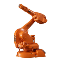
Required equipment
NoteArt. no.Equipment
Includes mechanical stop,
damper and attachment bolts.
3HAC026120-001Working range limit axis 2
Art. no. is specified in section
References on page 10.
-Technical reference manual - System
parameters
Installation of mechanical stop, axis 2
The procedure below details how to install the mechanical stop to axis 2.
Note/IllustrationAction
DANGER
Turn off all:
• electric power supply
• hydraulic pressure supply
• air pressure supply
to the robot, before entering the robot working
area.
1
Attachment holes are shown in the
figure Illustration, mechanical stop,
axis 2 on page 106.
Fit the mechanical stop to the frame, without
tightening the bolts.
2
xx0400001292
Make sure that the stop is in contact with the
lower boss on the gearbox, as the arrow shows
in the figure to the right.
3
Note! It is important that the mech-
anical stop is fitted in contact with
the lower boss on the gearbox!
2 pcs; M8 x 35, tightening torque:
25 Nm.
Tighten the attachment bolts.4
Shown in the figure Illustration,
mechanical stop, axis 2 on page 106.
Fit the damper to the mechanical stop, with its
attachment screw and washer. Tighten the screw.
5
Continues on next page
Product manual - IRB 1600/1660 107
3HAC026660-001 Revision: W
© Copyright 2006-2018 ABB. All rights reserved.
2 Installation and commissioning
2.4.3 Installation of additional mechanical stop on axis 2
Continued

 Loading...