Chapter 2 2-125
System Verification and Performance Tests
Agilent 8753ET System Verification and Performance Tests
Transmission Test Port Input Frequency Response from 300 kHz to 3 GHz
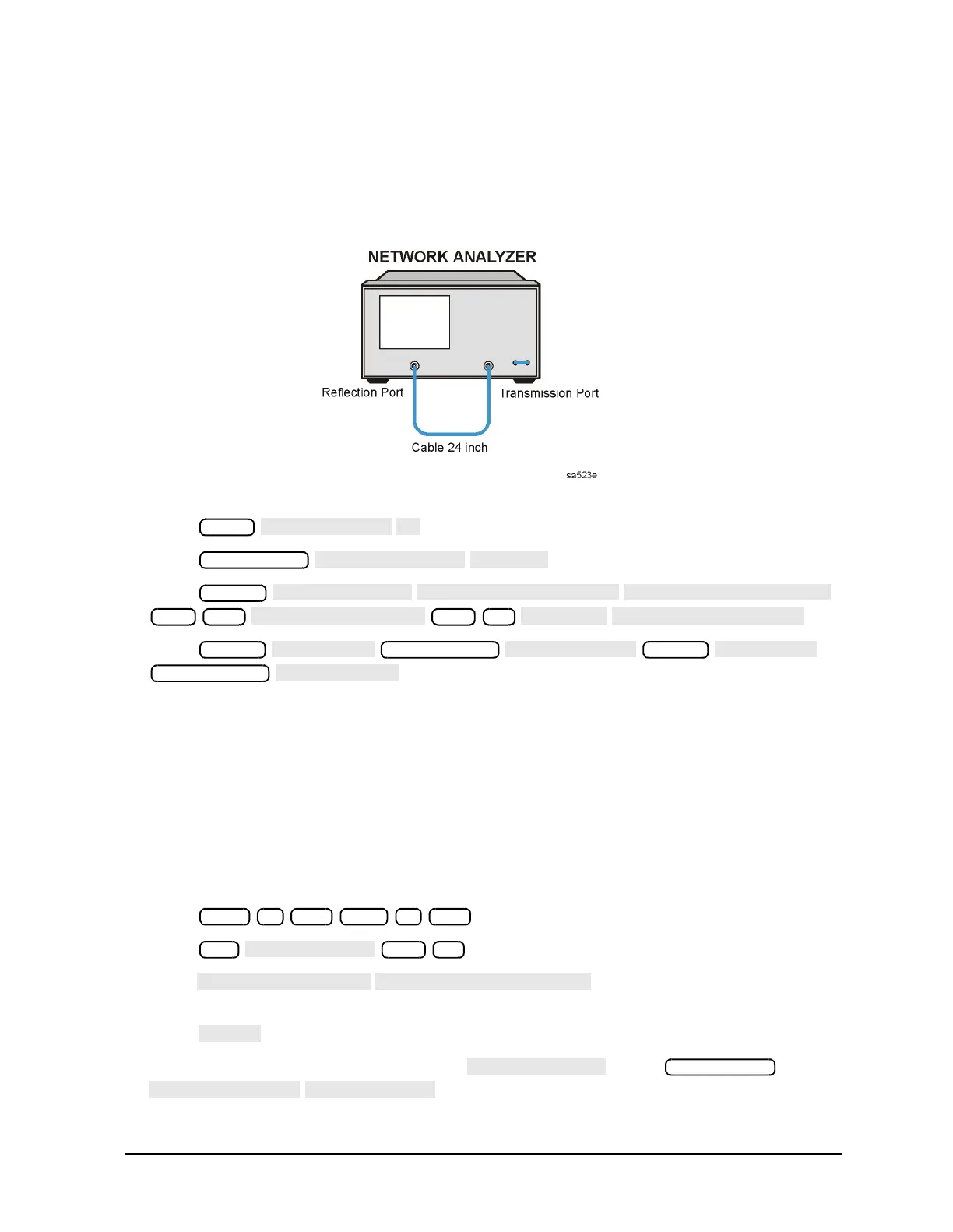
15.Connect the equipment as shown in Figure 2-70.
Figure 2-70 Transmission Test Port Input Frequency Response
16.Press .
17.Press .
18.Press
.
19.Press
.
20.Write the marker 1 or marker 2 value—whichever has the larger absolute
magnitude—in the performance test record.
21.If your analyzer does not have Option 006, this completes the test.
If your analyzer does have Option 006, continue with the following steps.
Power Meter Calibration for the Reflection Test Port
for 3 GHz to 6 GHz (Analyzers with Option 006)
22.Set up the analyzer as shown in Figure 2-69, using the 8481A power sensor. Cycle the
line power on the power meter. Zero and calibrate the power meter for this sensor.
23.Press .
24.Press .
25.Press . Press the appropriate softkeys
to build a calibration factor sensor table for the 8481A power sensor.
26.Press to exit the sensor calibration factor entries menu.
27.To select the 8481A power sensor, press . Press
.
Meas
Marker
300 k/m
−10 x1
∆
∆
Marker
Marker Search
Marker
Start 3 G/n Stop 6 G/n
Cal
−10
Sweep Setup

 Loading...


