7-22 Chapter 7
Source Troubleshooting
Phase Lock Error
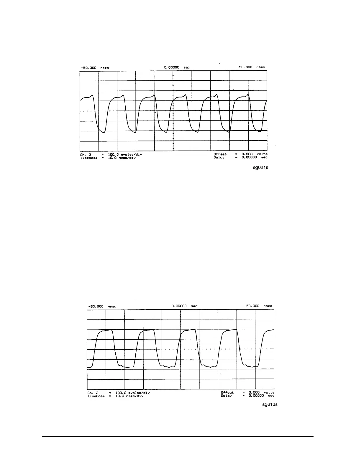
Figure 7-19 60 MHz HI OUT Waveform from A14J1
A14 VCO Exercise
The nominal tuning voltage range of the VCO is +10 to −5 volts. When the analyzer is in
operation, this voltage is supplied by the A13 assembly. This procedure substitutes a
power supply for the A13 assembly to check the frequency range of the A14 VCO.
1. Switch off the analyzer and remove the A13 assembly.
2. Put the A14 assembly on an extender board and switch on the instrument.
3. Prepare to monitor the VCO frequency, either by:
• Activating the analog bus and setting the internal counter to the FRACN node, or
• Connecting an oscilloscope to A14J2 (labeled LO OUT) and looking for waveforms
similar to Figure 7-20.
Figure 7-20 LO OUT Waveform at A14J2

 Loading...


