10-28 Chapter 10
Service Key Menus and Error Messages
Service Key Menus
Node 7 Log (log amplifier output detector)
Perform step A3 to set up a power sweep on the analog bus. Then press
.
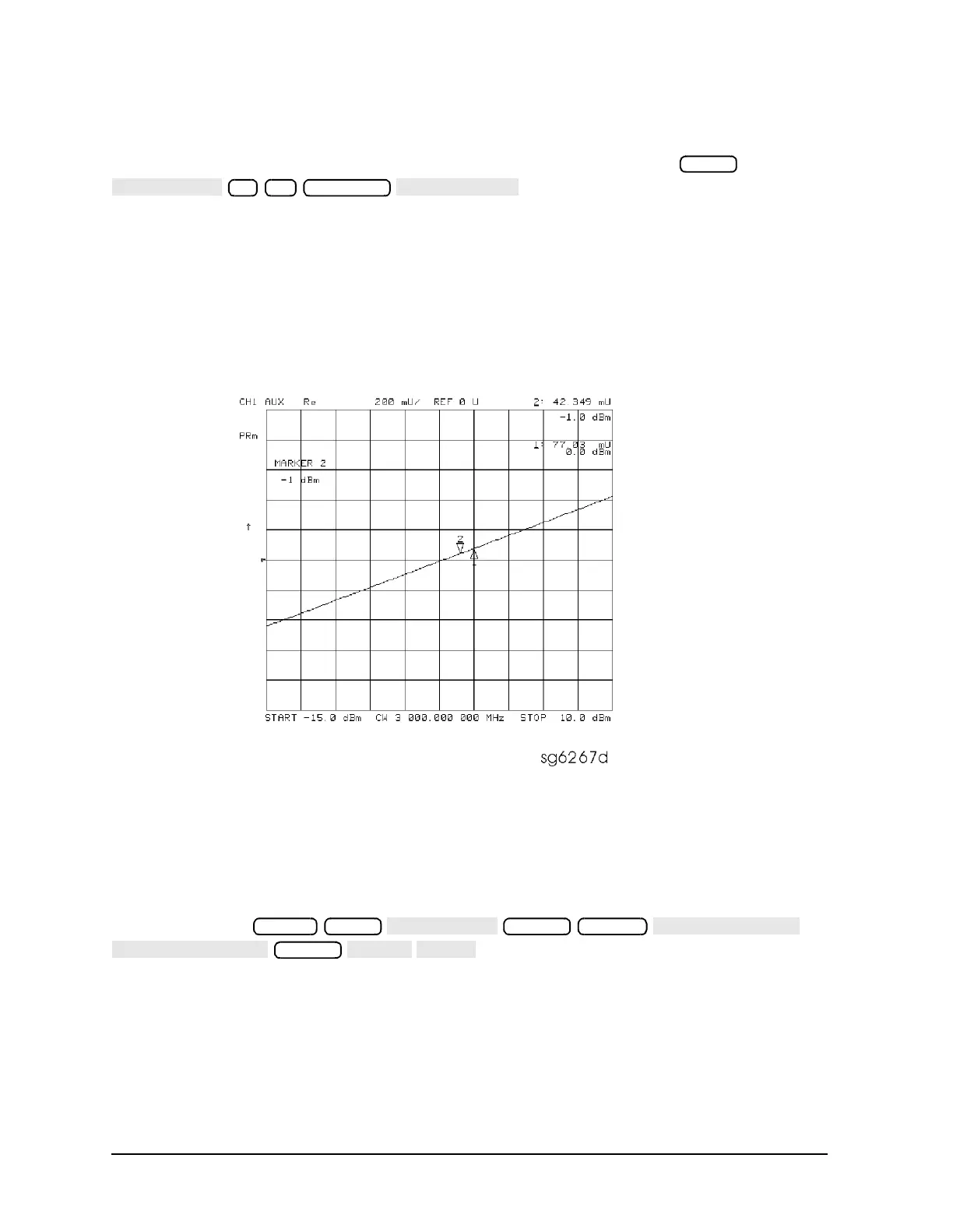
Node 7 displays the output of a logger circuit in the ALC loop. The trace should be a linear
ramp with a slope of 33 mv/dB with approximately 0 volts at −3 dBm. Absolute voltage
level variations are normal. Flat segments indicate ALC saturation and should not occur
between −15 dBm and +10 dBm.
The proper waveform at node 7 indicates that the circuits in the A3 source ALC loop are
normal and the source is leveled.
Figure 10-8 Analog Bus Node 7
Node 8 A3 Gnd (ground)
A10 Digital IF To observe the A10 analog bus nodes, perform step A10, below. Then
follow the node-specific instructions.
Step A10: Press:
.
Meas
7 x1
Preset Meas
Marker System
Format

 Loading...


