Chapter 2 2-39
System Verification and Performance Tests
Agilent 8753ES System Verification and Performance Tests
i. Press and use the front panel knob to scroll through the sensor
calibration factors table. Check to be sure all values are entered correctly. If you spot
an error, use the front panel knob to point to the data point you want to modify and
press .
13.Press the appropriate softkeys to create a power sensor calibration factors table.
14.Press to exit the sensor calibration factor entries menu.
15.Press to start the power meter
calibration.
Wait until the analyzer finishes the sweep, then continue with this procedure.
NOTE The analyzer displays the PC annotation, indicating the power meter
calibration is active.
Test Port 2 Input Frequency Response from 300 kHz to 3 GHz
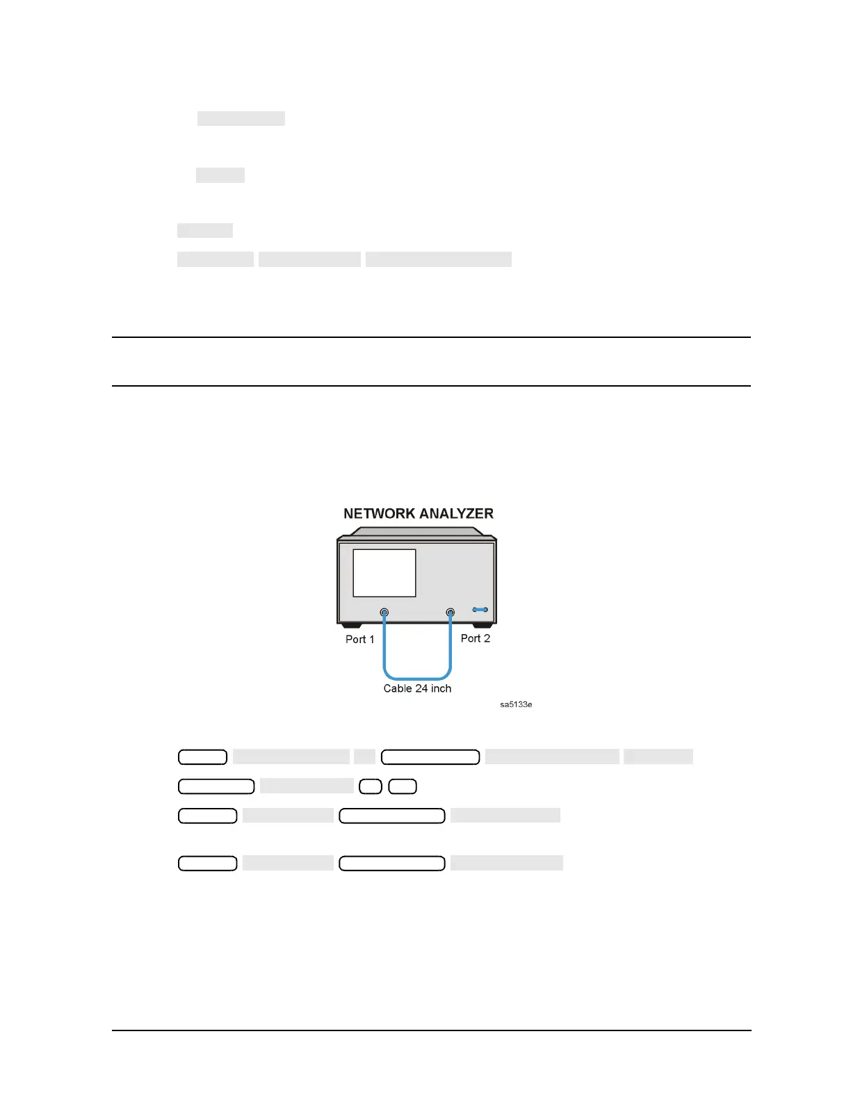
16.Connect the equipment as shown in Figure 2-19.
Figure 2-19 Test Port 2 Input Frequency Response Test Setup
17.Press .
18.Press .
19.Press to put marker 1 at the
minimum magnitude location of the trace.
20.Press to position marker 2 at
the maximum magnitude location of the trace.
21.Write the marker 1 or marker 2 value, whichever has the larger absolute magnitude, in
the performance test record.
Meas
Sweep Setup
Scale Ref
1
Marker
Marker Search
Marker
Marker Search

 Loading...


