140 Chapter 4
Basic Digital Operation
Using Waveform Markers
4. Name and store the waveform sequence “Storing Waveform Segments to Non-Volatile Memory” on
page 112.
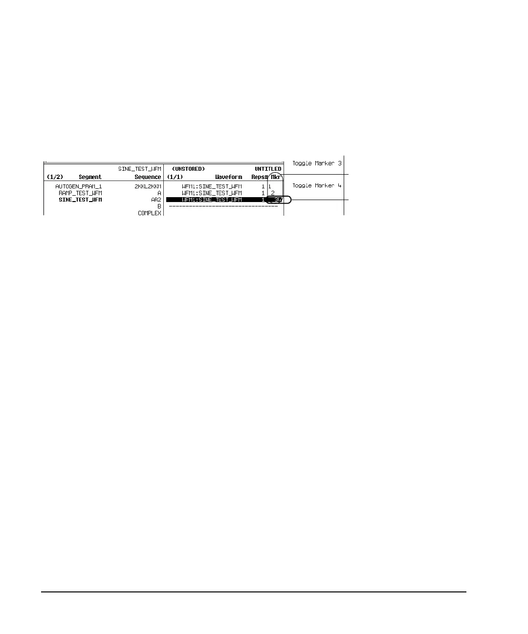
The following figure shows a sequence built reusing the same factory-supplied waveform segment; a
factory-supplied segment has a marker point on the first sample for all four markers. In this example,
Marker 1 is enabled for the first segment, Marker 2 is enable for the second segment, and markers 3 and 4
are enabled for the third segment.
For each segment, only the markers enabled for that segment produce a rear-panel auxiliary output signal. In
this example, the Marker 1 auxiliary signal appears only for the first segment, because it is disabled for the
remaining segments. The Marker 2 auxiliary signal appears only for the second segment, and the marker 3
and 4 auxiliary signals appear only for the third segment.
In an Existing Waveform Sequence
If you have not already done so, create and store a waveform sequence that contains at least three segments
(page 108). Ensure that the segment or segments are available in volatile memory (page 113).
1. Press
Mode > Dual ARB > Waveform Sequences, and highlight the desired waveform sequence.
2. Press
Edit Selected Waveform Sequence, and highlight the first waveform segment.
3. Press
Enable/Disable Markers > Toggle Marker 1, Toggle Mar ker 2 , Toggle Marker 3, and Toggle Marker 4.
Toggling a marker that has no marker points (page 137) has no effect on the auxiliary outputs.
An entry in the Mkr column indicates that the marker is enabled for that segment; no entry in the column
means that all markers are disabled for that segment
4. Highlight the next waveform segment and toggle the desired markers (in this example, markers 1 and 4).
5. Repeat Step 4 as desired (for this example, select the third segment and toggle marker 3).
Sequence Marker Column
This entry shows that
markers 3 and 4 are enabled
for this segment.