3 - 45
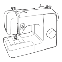
Upper shaft, Needle bar and Presser foot unit
Application of Assembly
Application
Application
Type B
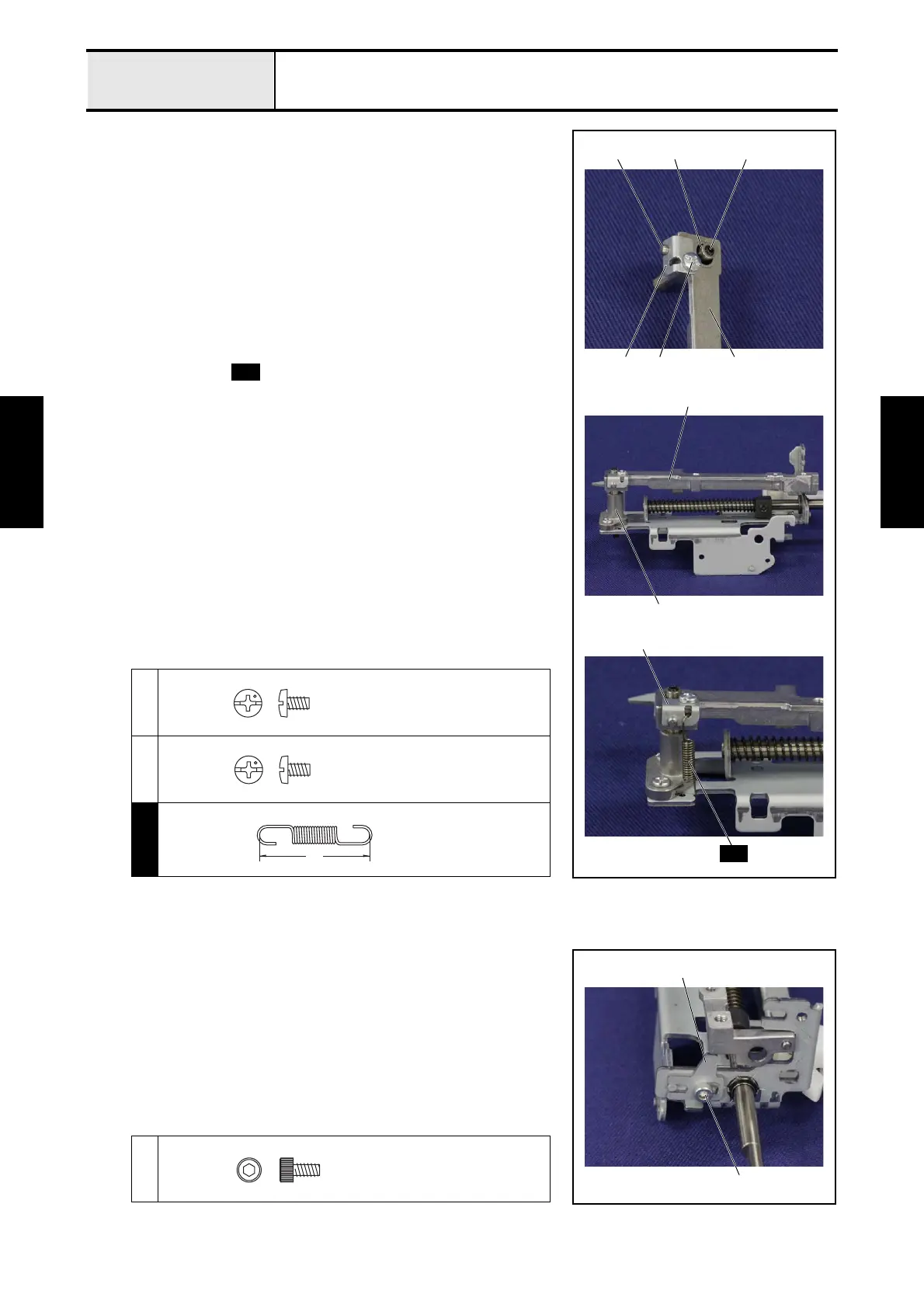
1. Insert the needle bar supporter shaft 1 into the upper side hole of the
needle bar supporter assy 2, and then align the hole of the needle bar
supporter assy 2 with the hole of the needle bar supporter shaft 1, and
then insert the shaft 3 until the position of the right figure.
2. Tighten the screw 1 temporarily.
3. Set the plate 4 to the needle bar supporter assy 2, and then secure it with
the screw 2.
*Key point
• Check that the groove part of the shaft 3 engaged with the
notch part of the plate 4.
4. Fully tighten the screw 1.
5. Insert the needle bar supporter shaft 1 to the shaft bushing 5.
6. Attach the spring to the plate 4 and the base holder assy.
<In case of Type A, refer to previous page.>
1
2
S09
1
4
1
2
3
2
S09
4
2
5
S09
Screw, Bind
M3X5
Screw, Bind
M3X5
25
SPRING
XE9140***
1-7 Attachment of Stopper L
1. Set the stopper L 1 to the bottom side of the base holder assy, and then
tighten the screw 1 temporarily.
*Key point
• Check that align the notch part of the stopper L 1 with the
boss of the base holder assy.
• Fully tighten the screw 1 after performing "4-8 Adjustment:
Needle bar supporter stopper L position".
1
1
1
Bolt, Socket
M3X6
 Loading...