2 - 49
Feed unit
Basic of Assembly
Basic
Basic
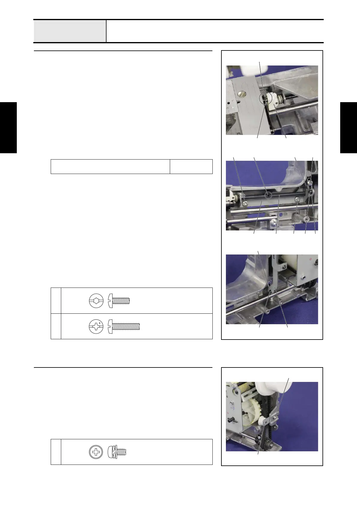
3 Attachment of Feed adjuster assy
1. Insert the groove 1 of the feed adjuster sub assy 2 to the shaft of the feed
arm assy 3, and then set the feed adjusting shaft holder 4 to the arm bed
with the screw 1 and the screw 2.
*Key point
• Tighten the screw 1 temporarily, fully tighten the screw 2
and fully tighten the screw 1 in this order.
2. Fully tighten the screw 3 of the feed connecting lever assy 5.
*Key point
• Set the positioning hole 6 of the feed adjuster sub assy 2 so
that facing directly frontward, and set the arm part 7 of the
feed connecting lever assy 5 so that facing directly frontward.
3. Set the hole of the connecting rod D 8 to the shaft 9 of the feed
connecting lever assy 5, and then attach the retaining ring E4 0.
→Refer to 3 - 75 of the Assembly.
Lubricate the EPNOC AP(N) 0 to the shaft 9 of
the feed connecting lever assy 5.
3mm dia. ball
1
2
3
4
2
12
3
1
2
9
0
8
356
79
Taptite, Bind S
M4X10
Screw, Bind
M4X16
4 Attachment of Tension pulley assy
1. Set the tension pulley assy 1 to the arm bed, and then tighten the screw 1
temporarily.
*Key point
• Fully tighten the screw 1 after performing "4-5 Adjustment:
Timing belt tension".
1
1
1
Screw, Pan (S/P washer)
M4X8DA
 Loading...