3 - 50
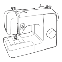
Upper shaft, Needle bar and Presser foot unit
Application of Assembly
Application
Application
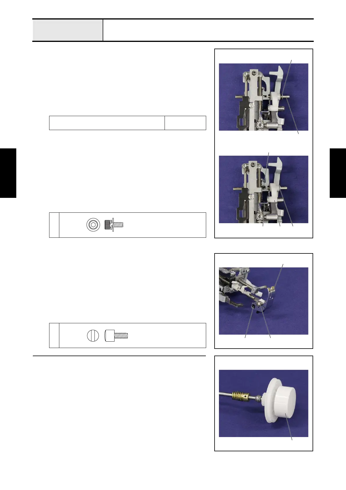
1-17 Attachment of Thread take-up lever link
1. Attach the retaining ring E4 1 to the shaft 2.
2. Set the base holder assy as shown in the right figure, and then insert the
shaft 2 into the washer, spring 3, the thread take-up lever link 4 and the
base holder assy from the right side, and then secure them with the screw
1.
*Key point
• Insert the shaft of the thread take-up lever 5 into the thread
take-up lever link 4.
Apply EPNOC AP (N) 0 to the all around the take-
up support shaft hole.
Small amount
XC8387***
1
2
1
4
1
5 3
Screw
3X8
1-18 Attachment of Presser foot holder assy
1. Set the presser foot holder assy 1 to the presser bar with the screw 1.
2. Set the zigzag presser foot 2 to the presser foot holder assy 1.
1
1
2
1
Screw
3.57
2 Assembly of Upper shaft assy
1. Set the pulley 1 to the upper shaft assy.
1
 Loading...