i
1. Outline of Mechanism ........................................................................1 - 1
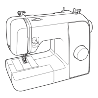
Main mechanisms ..............................................................................................1 - 2
Driveline .............................................................................................................1 - 3
Positions of electronic components ...................................................................1 - 6
Control system block diagram ...........................................................................1 - 7
2. Basic of Disassembly/Assembly .......................................................2 - 1
Disassembly
Main frame and Covers .....................................................................................2 - 2
Removal of Accessory table ..............................................................................................................2 - 3
Removal of Face plate assy ...............................................................................................................2 - 3
Removal of Pattern selecting dial ......................................................................................................2 - 3
Removal of Front cover assy .............................................................................................................2 - 4
Removal of Rear cover assy ..............................................................................................................2 - 5
Main motor unit ..................................................................................................2 - 6
Removal of Motor 3P supply assy .....................................................................................................2 - 7
Removal of Lower shaft plate ............................................................................................................2 - 8
Feed unit ............................................................................................................2 - 9
Removal of Tension pulley assy ......................................................................................................2 - 10
Removal of Feed adjuster assy ........................................................................................................2 - 10
Removal of Feed module .................................................................................................................2 - 11
Needle threading mechanism ..........................................................................2 - 12
Removal of Thread guard assy ........................................................................................................2 - 13
Zigzag mechanism ...........................................................................................2 - 14
Removal of Z dial assy ....................................................................................................................2 - 15
Removal of Zigzag connecting rod assy ..........................................................................................2 - 15
Removal of Zigzag link holder assy ................................................................................................2 - 16
Feed control mechanism .................................................................................2 - 17
Removal of Reverse sewing lever A ................................................................................................2 - 18
Removal of Reverse sewing lever B assy ........................................................................................2 - 19
Removal of Lever holder assy .........................................................................................................2 - 19
Removal of Feed bracket assy .........................................................................................................2 - 20
Buttonhole and Pattern selecting mechanism .................................................2 - 21
Removal of BH adjusting plate ........................................................................................................2 - 22
Removal of BH connecting shaft .....................................................................................................2 - 23
Removal of BH stopper assy ...........................................................................................................2 - 24
Removal of Pattern selecting unit assy ............................................................................................2 - 24
Upper shaft, Needle bar and Presser foot unit ................................................2 - 25
Removal of Upper shaft assy ...........................................................................................................2 - 26
Removal of Stopper plate ................................................................................................................2 - 26
Removal of Needle-presser module .................................................................................................2 - 27
Assembly
Upper shaft, Needle bar and Presser foot unit ................................................2 - 28
Attachment of Needle-presser module ............................................................................................2 - 29
Attachment of Stopper plate ............................................................................................................2 - 29
Attachment of Upper shaft assy .......................................................................................................2 - 30
 Loading...